Amplification method adopting low-cost overclocking high-speed transimpedance amplifier

A transimpedance amplifier, low-cost technology, applied in the field of communication, can solve the problems of cost saving, dynamic range reduction, bandwidth reduction, etc., to achieve the effect of ensuring sensitivity and dynamic range, reducing input equivalent noise, and reducing design cost

Pending Publication Date: 2022-02-15
成都明夷电子科技有限公司
View PDF0 Cites 0 Cited by
  • Summary
  • Abstract
  • Description
  • Claims
  • Application Information

AI Technical Summary

Problems solved by technology

[0003] However, the bandwidth of 3.5GHz photodiodes is much lower than that of 7GHz photodiodes. Under the premise of ensuring the same performance, how to overcome the reduction of bandwidth caused by the use of low-bandwidth photodiodes and avoid the bandwidth of the system combining photodiodes and transimpedance amplifiers The influence of the intersymbol interference generated by the reduction on the sensitivity has become a difficult problem
[0004] In addition, the process selection of the transimpedance amplifier itself must also avoid expensive special processes such as SiGe, and cannot be better than the mainstream design of CMOS processes at current transmission rates, otherwise it will violate the original intention of saving costs
Therefore, limited by the process performance, the transimpedance amplifier needs to overcome other problems such as the increase of noise, the increase of group delay change, the reduction of dynamic range and the increase of power consumption while the bandwidth is increased.

Method used


Image

  • Amplification method adopting low-cost overclocking high-speed transimpedance amplifier
  • Amplification method adopting low-cost overclocking high-speed transimpedance amplifier
  • Amplification method adopting low-cost overclocking high-speed transimpedance amplifier

Examples


Embodiment 1

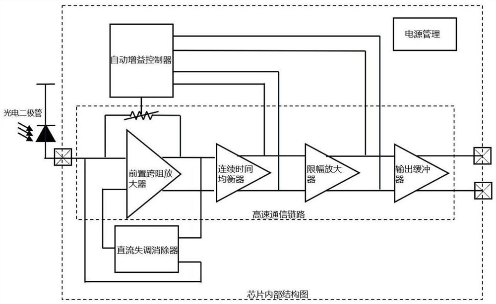
[0058] This embodiment proposes a method for realizing an overfrequency high-speed transimpedance amplifier with low cost, such as figure 1 , figure 2 shown, including the following operations:

[0059] Step 1: Build an overfrequency high-speed transimpedance amplifier connected to the photodiode; the overfrequency high-speed transimpedance amplifier includes a high-speed communication link, a low-speed control circuit and a power management unit; the high-speed communication link unit includes a pre-transimpedance amplifier, A continuous time equalizer, a limiting amplifier, and an output buffer; the low-speed control circuit includes a DC offset canceller and an automatic gain controller;

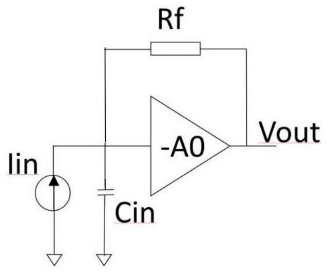
[0060] The pre-transimpedance amplifier includes a feedforward amplifier unit and a feedback resistance unit; the feedback resistance unit is lapped between the output end and the input end of the feedforward amplifier unit;

[0061] The input end of described feed-forward amplifier un...

Embodiment 2

[0084] In this embodiment, on the basis of the above-mentioned embodiment 1, in order to better realize the present invention, further, two digital output control channels and an automatic gain digital controller are set in the automatic gain controller; one digital output The control channel includes a common-mode voltage extraction unit, a threshold voltage generator, a peak detector, and a hysteresis comparator; one of the two digital output control channels passes through the two input terminals of the peak detector and the continuous time equalizer The two output terminals are connected, and the other digital output control channel is connected to the two output terminals of the limiting amplifier through the two input terminals of the peak detector;

[0085] In the step 6.4:

[0086] First, connecting the common-mode voltage extraction unit between the two input terminals of the peak detector for extracting the common-mode voltage;

[0087] Then, the common-mode voltage...

Embodiment 3

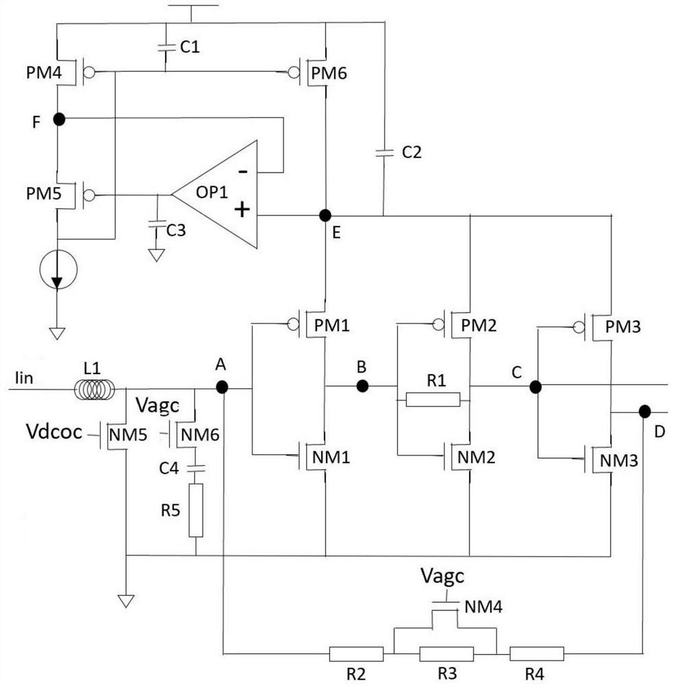
[0094] This embodiment proposes a low-cost overfrequency high-speed transimpedance amplifier, which is connected to the photodiode and receives the current signal Iin sent by the photodiode, and the current signal Iin includes a DC component and an AC component; as figure 1 , figure 2 , image 3 As shown, the overfrequency high-speed transimpedance amplifier includes a high-speed communication link, a low-speed control circuit and a power management unit;

[0095] The high-speed communication link unit includes a pre-transimpedance amplifier, a continuous time equalizer, a limiting amplifier, and an output buffer; the low-speed control circuit includes a DC offset canceller and an automatic gain controller;

[0096] The pre-transimpedance amplifier includes a feedforward amplifier unit and a feedback resistance unit; the feedback resistance unit is lapped between the output end and the input end of the feedforward amplifier unit;

[0097] The input end of described feed-for...


PUM


Abstract

The invention provides an amplification method adopting a low-cost overclocking high-speed transimpedance amplifier. The overclocking high-speed transimpedance amplifier comprises a high-speed communication link, a low-speed control circuit and a power management unit. The high-speed communication link unit comprises a front transimpedance amplifier, a continuous time equalizer, a limiting amplifier and an output buffer; the low-speed control circuit comprises a direct-current offset canceller and an automatic gain controller; the front transimpedance amplifier comprises a feed-forward amplifier unit and a feedback resistor unit; and the feedback resistor unit is lapped between the output end and the input end of the feed-forward amplifier unit. Through the arrangement, the bandwidth of a system combined with the low-speed photodiode is extended, and the possibility of overclocking is ensured; meanwhile, the associated problem caused by process performance limitation is also solved, and the sensitivity and the dynamic range of the system are ensured; and conventional circuit components are adopted, so that a low-cost scheme becomes possible.

Description

technical field [0001] The invention belongs to the technical field of communication, and in particular relates to an amplification method using a low-cost overfrequency high-speed transimpedance amplifier. Background technique [0002] Reducing the cost of optical communication under the premise of increasing communication speed and ensuring transmission quality is the key for modern companies to win in market competition. In the field of 10G PON optical communication, in order to further reduce communication costs, it is first necessary to start with optical devices that account for a large proportion of the cost. On the front-end side of the optical receiver, changing the avalanche photodiode APD adapted to the transimpedance amplifier TIA from a high-bandwidth product to a lower-bandwidth product is one of the starting directions, such as replacing the original bandwidth of about 7GHz photodiode with a bandwidth 3.5GHz or lower photodiodes. [0003] However, the bandwi...

Claims


Application Information

Patent Timeline
Patent Type & Authority Applications(China)
IPC IPC(8): H03F1/26H03F1/48H03F3/45H03G3/30H03G11/00
CPCH03F1/26H03F1/483H03F3/45179H03G3/30H03G11/00
Inventor 赵欣王睿蔡之骏雷春桃陶蕤毛毅
Owner 成都明夷电子科技有限公司
Why Eureka
Try Eureka