
Oil supply detection device for engine of lifeboat of ship

A detection device and engine technology, applied in the direction of engine components, machines/engines, pump devices, etc., can solve problems such as reducing engine oil supply efficiency, unable to adjust the oil supply balance independently, and engine stop.

Pending Publication Date: 2022-02-15
张雅楠
View PDF0 Cites 0 Cited by
  • Summary
  • Abstract
  • Description
  • Claims
  • Application Information

AI Technical Summary

Problems solved by technology

[0002] Due to the limited installation space of ship lifeboats and rescue boats, the engine oil supply tank and oil supply piping system are often arranged at the lower part of the engine, so the fuel has no injection height to the engine, and the oil supply system of the engine is in a state of negative pressure during startup or operation. , thus causing the engine to stop working, therefore, it is necessary to develop a fuel supply system detector for the lifeboat fuel supply system to prevent the lifeboat from being unable to start due to a problem with the engine fuel supply system
[0003] The oil supply detection device for ship lifeboat engine is a device for detecting the efficiency of oil supply for the lifeboat engine oil supply system. Generally, the oil supply detection device for ship lifeboat engine cannot automatically adjust the oil supply balance when the oil supply is abnormal. The efficiency of engine oil supply has been reduced, and an oil supply detection device for marine lifeboat engines is urgently needed

Method used


Image

  • Oil supply detection device for engine of lifeboat of ship
  • Oil supply detection device for engine of lifeboat of ship
  • Oil supply detection device for engine of lifeboat of ship

Examples


Embodiment

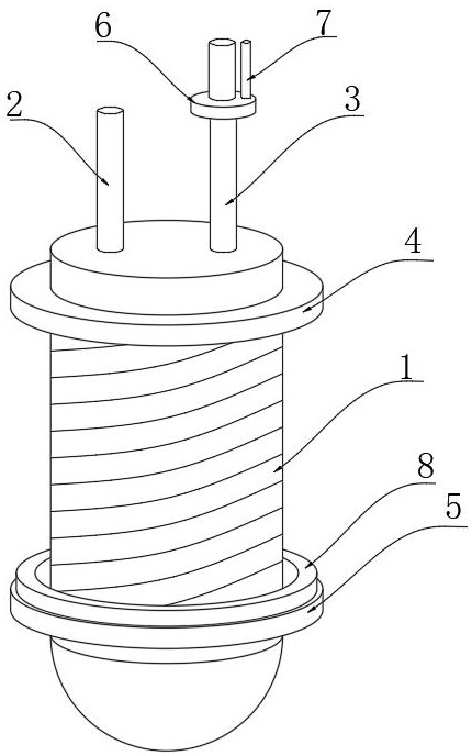
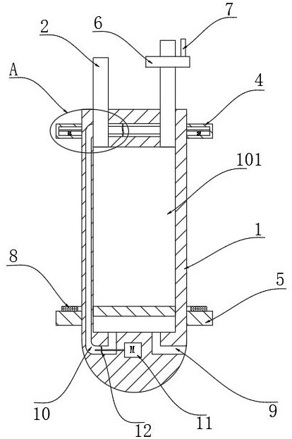
[0025] refer to Figure 1-4 , an oil supply detection device for a marine lifeboat engine, comprising a columnar oil supply tank 1, the oil supply tank 1 is installed on the lower side of the lifeboat, and the oil supply tank 1 is submerged in water when the ship is working, and the oil supply tank 1 is hollow structure and its upper end is connected with oil inlet pipe 2 and oil delivery pipe 3, and the lower ends of oil inlet pipe 2 and oil delivery pipe 3 are equipped with check valves, and the check valve at oil inlet pipe 2 allows liquid to flow from oil inlet pipe 2 to oil supply in one direction. In the tank 1, the one-way valve at the oil delivery pipe 3 allows the liquid to flow from the oil supply tank 1 to the oil inlet pipe 2 in one direction. 1. When the oil pressure at the oil inlet end of the engine is insufficient, the oil can be pumped from the oil inlet pipe 2 and then pumped to the oil inlet end of the engine through the oil delivery pipe 3, so as to ensure ...


PUM


Abstract

The invention discloses an oil supply detection device for an engine of a lifeboat of a ship. The oil supply detection device comprises a columnar oil supply tank, the oil supply tank is of a hollow structure, the upper end of the oil supply tank communicates with an oil inlet pipe and an oil conveying pipe, and the lower end of the oil inlet pipe and the lower end of the oil conveying pipe are each provided with a one-way valve; the one-way valve at the oil inlet pipe allows liquid to flow into the oil supply tank from the oil inlet pipe in a one-way mode, the one-way valve at the oil conveying pipe allows liquid to flow into the oil inlet pipe from the oil supply tank in a one-way mode, the oil inlet pipe is communicated with an external oil tank, and the oil conveying pipe is communicated with the oil inlet end of a ship engine. The oil supply detection device has the advantages that when the oil pressure of the oil inlet end of an engine is low and normal oil supply cannot be met, the two baffles get close to each other and do not seal the oil supply pipe, the lower ring body floats upwards due to the fact that the density of the lower ring body is far smaller than that of water, and the magnetic ring moves synchronously along with the lower ring body in the floating process and drives the oil supply piston to move upwards through magnetic attraction force; oil in the oil supply tank is extruded to enter the oil inlet end of the engine through the oil supply pipe, and normal oil supply of the engine is guaranteed.

Description

technical field [0001] The invention relates to the technical field of oil supply detection, in particular to an oil supply detection device for marine lifeboat engines. Background technique [0002] Due to the limited installation space of ship lifeboats and rescue boats, the engine oil supply tank and oil supply piping system are often arranged at the lower part of the engine, so the fuel has no injection height to the engine, and the oil supply system of the engine is in a state of negative pressure during startup or operation. , thus causing the engine to stop working. Therefore, it is necessary to develop a fuel supply system detector for the lifeboat fuel supply system to prevent the lifeboat from being unable to start due to a problem with the engine fuel supply system. [0003] The oil supply detection device for ship lifeboat engine is a device for detecting the efficiency of oil supply for the lifeboat engine oil supply system. Generally, the oil supply detection d...

Claims


Application Information

Patent Timeline
IPC IPC(8): F02M37/00F02M37/04F02B77/08F04D13/06
CPCF02M37/0076F02M37/04F02B77/08F04D13/06
Inventor 张雅楠
Owner 张雅楠
Learn More