
Flexible lower limb exoskeleton control method, exoskeleton control system and use method

A control method and control system technology, applied in the field of rehabilitation equipment, can solve the problems of single foot, the pressure point is not necessarily accurate, the pressure data of the sole of the foot cannot be visualized, and the judgment of the rehabilitation situation, etc., to achieve the effect of being easy to wear and simple in structure.

Pending Publication Date: 2022-02-15
HUNAN UNIV
View PDF22 Cites 0 Cited by
  • Summary
  • Abstract
  • Description
  • Claims
  • Application Information

AI Technical Summary

Problems solved by technology

[0004] However, the existing flexible lower extremity exoskeleton has the following deficiencies: 1. There is a big problem in the input source of the existing flexible lower extremity exoskeleton: the plantar pressure monitoring system installs pressure sensors in the insole, and due to the contact between the sole of the foot and the human body when walking There is inevitable relative sliding between the insoles, so the monitored pressure points may not be accurate; 2. The existing flexible lower extremity exoskeleton is mainly aimed at improving gait symmetry, (due to product weight, space size, etc.) Lifting, failed to achieve the rehabilitation of patients with bipedal weakness; 3. The plantar pressure data of the existing flexible lower limb exoskeleton cannot be visualized and the rehabilitation status can be judged. It can only be judged by the motion capture system or doctor's experience whether the patient's gait has improved

Method used


Image

  • Flexible lower limb exoskeleton control method, exoskeleton control system and use method
  • Flexible lower limb exoskeleton control method, exoskeleton control system and use method
  • Flexible lower limb exoskeleton control method, exoskeleton control system and use method

Examples


Embodiment Construction

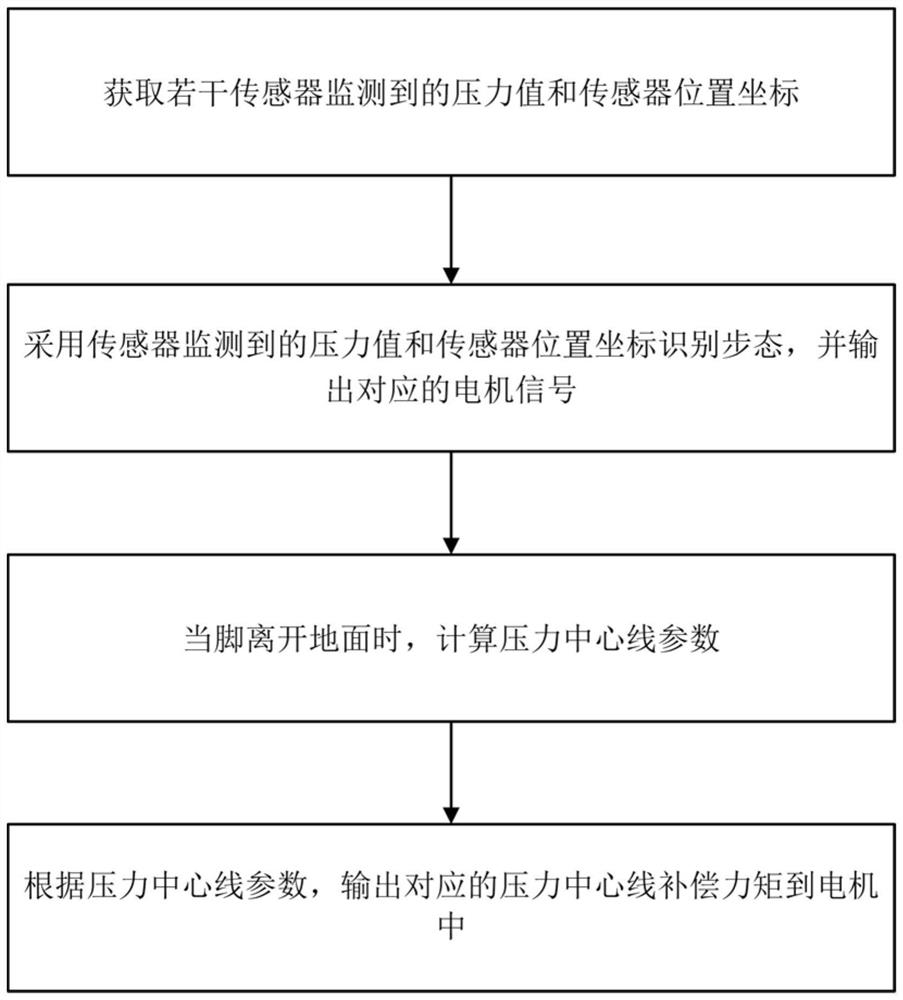
[0047] like figure 1 It is a schematic flow chart of the exoskeleton control method of the present invention: the flexible lower limb exoskeleton control method provided by the present invention includes the following steps:

[0048] S1. Obtain pressure values ​​and sensor position coordinates monitored by several sensors;

[0049] S2. Use the pressure value monitored by the sensor and the sensor position coordinates to identify the gait, and output the corresponding motor signal;

[0050] S3. When the foot leaves the ground, calculate the pressure centerline parameter;

[0051] S4. According to the pressure centerline parameters, output the corresponding pressure centerline compensation torque to the motor.

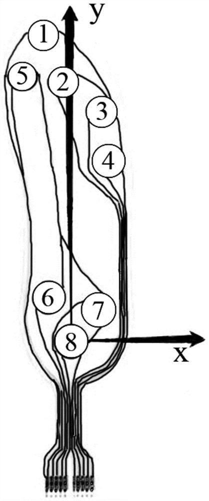
[0052] The sensors in step S1 in this embodiment include a first pressure sensor, a second pressure sensor, a third pressure sensor, a fourth pressure sensor, a fifth pressure sensor, a sixth pressure sensor, a seventh pressure sensor, a Eight pressure sensors and ine...


PUM


Abstract

The invention discloses a flexible lower limb exoskeleton control method. The method comprises the steps of obtaining the pressure values monitored by a plurality of sensors and the position coordinates of the sensors; recognizing the gait through the pressure values monitored by the sensors and the position coordinates of the sensors, and outputting a corresponding motor signal; when the feet leave the ground, calculating the pressure center line parameters; and according to the pressure center line parameters, outputting the pressure center line compensation torque. The invention further discloses an exoskeleton control system based on the flexible lower limb exoskeleton control method and a using method of the exoskeleton control system. Through a plantar pressure sensor and an inertial sensor, a plantar pressure center line is calculated through the relative change, and the risk that pressure collection positions are inconsistent is avoided; other sensors are not needed for auxiliary measurement; wearing is easy and convenient, the structure is simple, and the rehabilitation of a patient suffering from foot sole myasthenia can be achieved; the closed-loop control can be achieved, the plantar pressure center line is output in real time, and the current rehabilitation condition of the patient is judged immediately and conveniently.

Description

technical field [0001] The invention belongs to the field of rehabilitation equipment, and in particular relates to a flexible lower limb exoskeleton control method, an exoskeleton control system and a use method. Background technique [0002] In today's medical environment, rehabilitation equipment has great significance for patients. Exoskeleton technology is often used when patients are unable to stabilize their posture due to illness. The walking gait is divided into dorsiflexion (toe lift) and plantar flexion (heel lift). The lower extremity exoskeleton is mainly used to correct patients with abnormal gait. Take plantar muscle weakness as an example. Insufficient muscle strength, the forefoot cannot be warped when walking, and it keeps drooping, which will lead to less abnormal and difficult walking. [0003] Nowadays, flexible lower extremity exoskeletons are usually used to solve the walking problem of patients. The existing flexible lower extremity exoskeleton use...

Claims


Application Information

Patent Timeline
IPC IPC(8): B25J9/00B25J9/16
CPCA61H3/00A61H2201/5071A61H2201/1659A61H2201/5058A61H2201/1207A61H2003/007
Inventor 莫富灏吴柯田野
Owner HUNAN UNIV
Learn More