
Auxiliary welding equipment for box type steel component and machining process of auxiliary welding equipment

A technology of auxiliary equipment and section steel, applied in welding/cutting auxiliary equipment, welding equipment, welding equipment, etc., can solve the problems of low processing efficiency, difficult to guarantee product quality, easy to produce deviation, etc., to improve processing efficiency and improve position accuracy. degree, the effect of ensuring product quality

Active Publication Date: 2022-02-15
北钢建设集团股份有限公司
View PDF10 Cites 6 Cited by
  • Summary
  • Abstract
  • Description
  • Claims
  • Application Information

AI Technical Summary

Problems solved by technology

[0004] However, manual scribing and manual temporary fixing of the post-installation methods are restricted by human factors, and the processing efficiency is low; moreover, deviations are likely to occur during marking or temporary fixing, and it is difficult to guarantee product quality requirements
[0005] Regarding the related technologies mentioned above, the inventor believes that there are defects such as low processing efficiency and difficulty in guaranteeing product quality

Method used


Image

  • Auxiliary welding equipment for box type steel component and machining process of auxiliary welding equipment
  • Auxiliary welding equipment for box type steel component and machining process of auxiliary welding equipment
  • Auxiliary welding equipment for box type steel component and machining process of auxiliary welding equipment

Examples


Embodiment

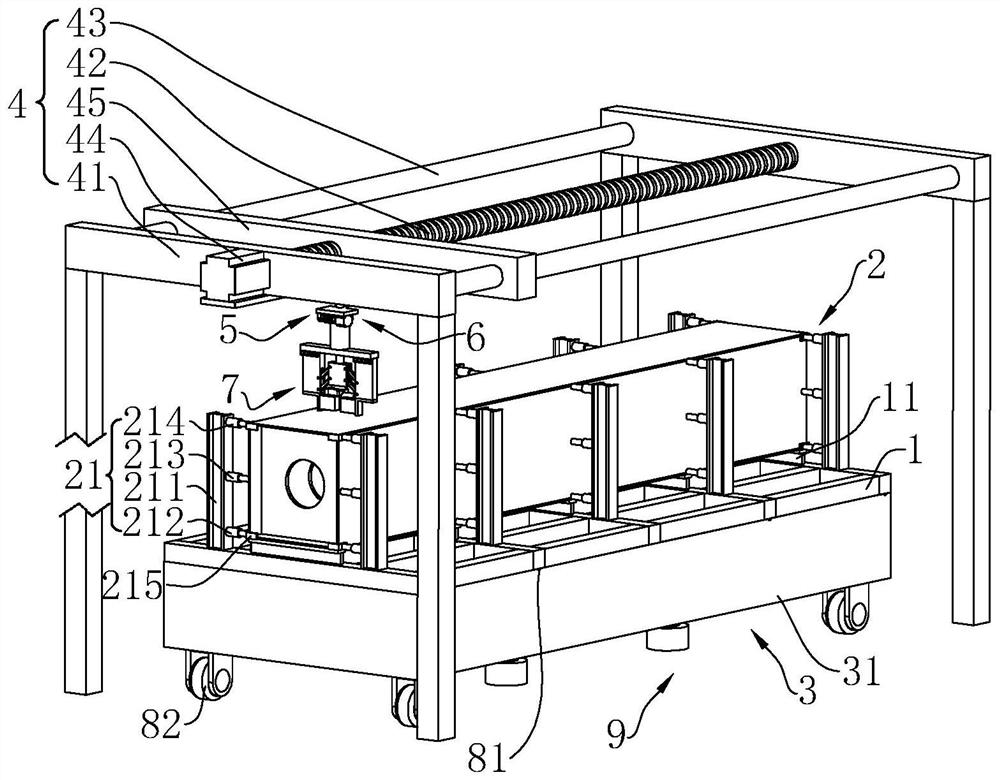
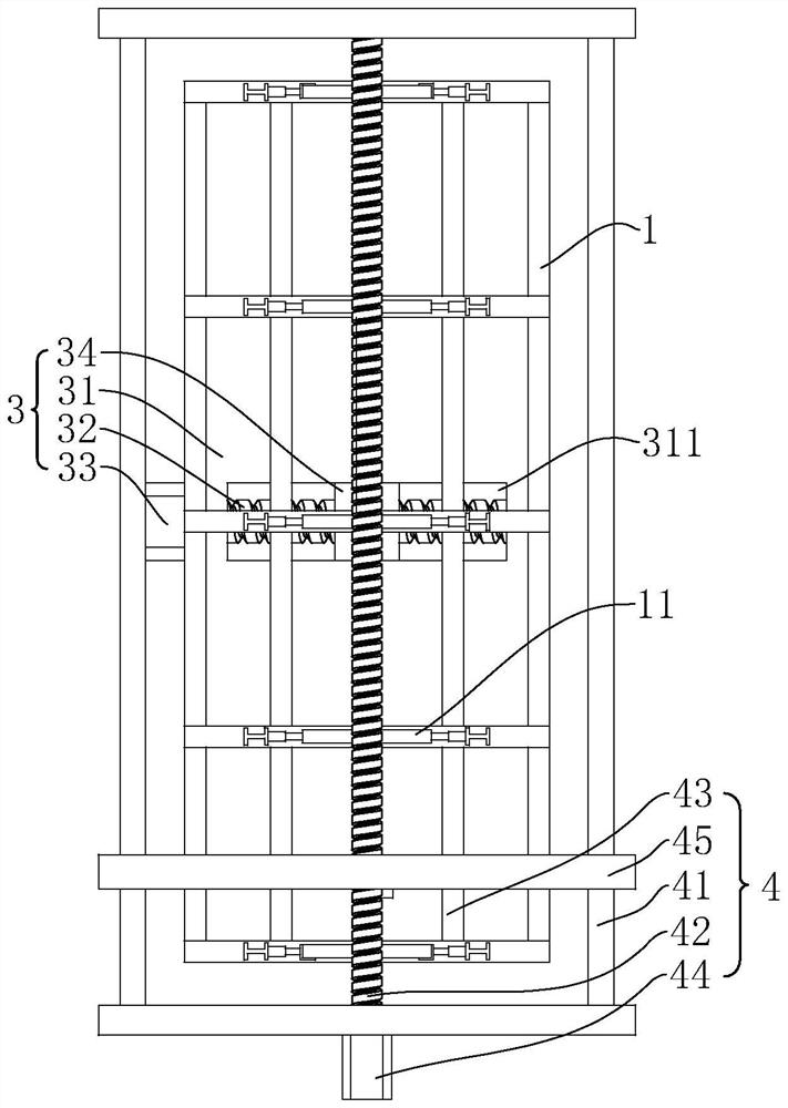
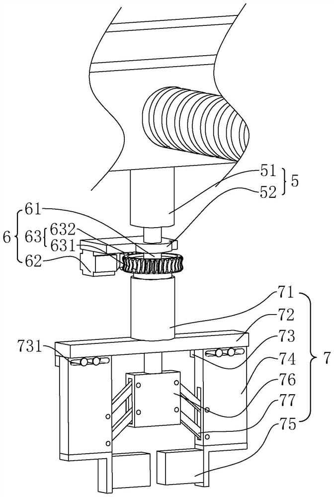
[0068] A welding auxiliary equipment for box-shaped steel members, referring to figure 1 , including a tire frame 1, a main body positioning device, a welding support device and a control system. The main body positioning device is arranged on the tire frame 1, and the main body positioning device is used for positioning the bottom plate and the top plate. The welding support device temporarily fixes the partition and side plates during welding. The control system is used to control the main body positioning device and the welding support device. The control system is a programmable logic controller.

[0069] The tire frame 1 is a rectangular frame, and the top of the tire frame 1 is fixedly connected with a plurality of support plates 11 at intervals along its length direction. Width, when the box-shaped steel member is welded, the bottom plate is first placed on a plurality of support plates 11 .

[0070] The main body positioning device includes two sets of positioning ...


PUM


Abstract

The invention discloses auxiliary welding equipment for a box type steel component and a machining process of the auxiliary welding equipment, and relates to the technical field of steel structure machining. The auxiliary welding equipment for the box type steel component comprises a jig frame and further comprises a main body positioning device, a welding supporting device and a control system; the main body positioning device is used for fixing and positioning a bottom plate and a top plate; the welding supporting device is used for temporarily fixing and positioning partition plates and side plates; and the control system is a programmable logic controller and is electrically connected with the positioning device and the welding supporting device. In the auxiliary welding equipment, the design positions of all parts of the box-type steel component are programmed in the control system, then the main body positioning device and the welding supporting device are controlled to work through the control system, and all the parts of the box-type steel component are positioned, so that the position accuracy of all the parts of the box-type steel component is improved, and the product quality of the box type steel component is ensured; and the processing efficiency is greatly improved.

Description

technical field [0001] The present application relates to the technical field of steel structure processing, in particular to a welding auxiliary equipment for box-shaped steel components and a processing technology thereof. Background technique [0002] Steel members refer to steel structural composite members that can bear and transmit loads and are connected by steel plates, angle steels, channel steels, I-beams, welded or hot-rolled H-beams, cold-bent or welded through connectors. Among them, there are many parts in the box-shaped steel member, and the requirements for the position of each part are relatively high during welding. [0003] At present, when welding and assembling box-shaped steel components, it is necessary to position and fix the base plate on the tire frame first, and then mark the positions of other rear panels (partition plates, side plates, and roof plates) on the base plate. When welding the rear mounting plate, it is necessary to position the rear ...

Claims


Application Information

Patent Timeline
Patent Type & Authority Applications(China)
IPC IPC(8): B23K37/04B23K9/02B23K9/18B23K9/16B23K9/235B23K9/32B23K28/02B23P15/00
CPCB23K37/0426B23K9/02B23K9/18B23K9/16B23K9/235B23K9/32B23K28/02B23P15/00B23K2103/04
Inventor 姜昊潘蓉
Owner 北钢建设集团股份有限公司
Learn More