Automatic iron tamping machine tool controlled at high temperature
A technology that controls automation and iron quality, and is applied to forging/pressing/hammering machinery, power hammers, manufacturing tools, etc. It can solve the problems of laborious replacement of rammer molds, etc., to improve the life of the device, improve the efficiency of tamping, and improve the impact rate. The effect of hitting
- Summary
- Abstract
- Description
- Claims
- Application Information
AI Technical Summary
Problems solved by technology
Method used
Image

Examples
Embodiment 1
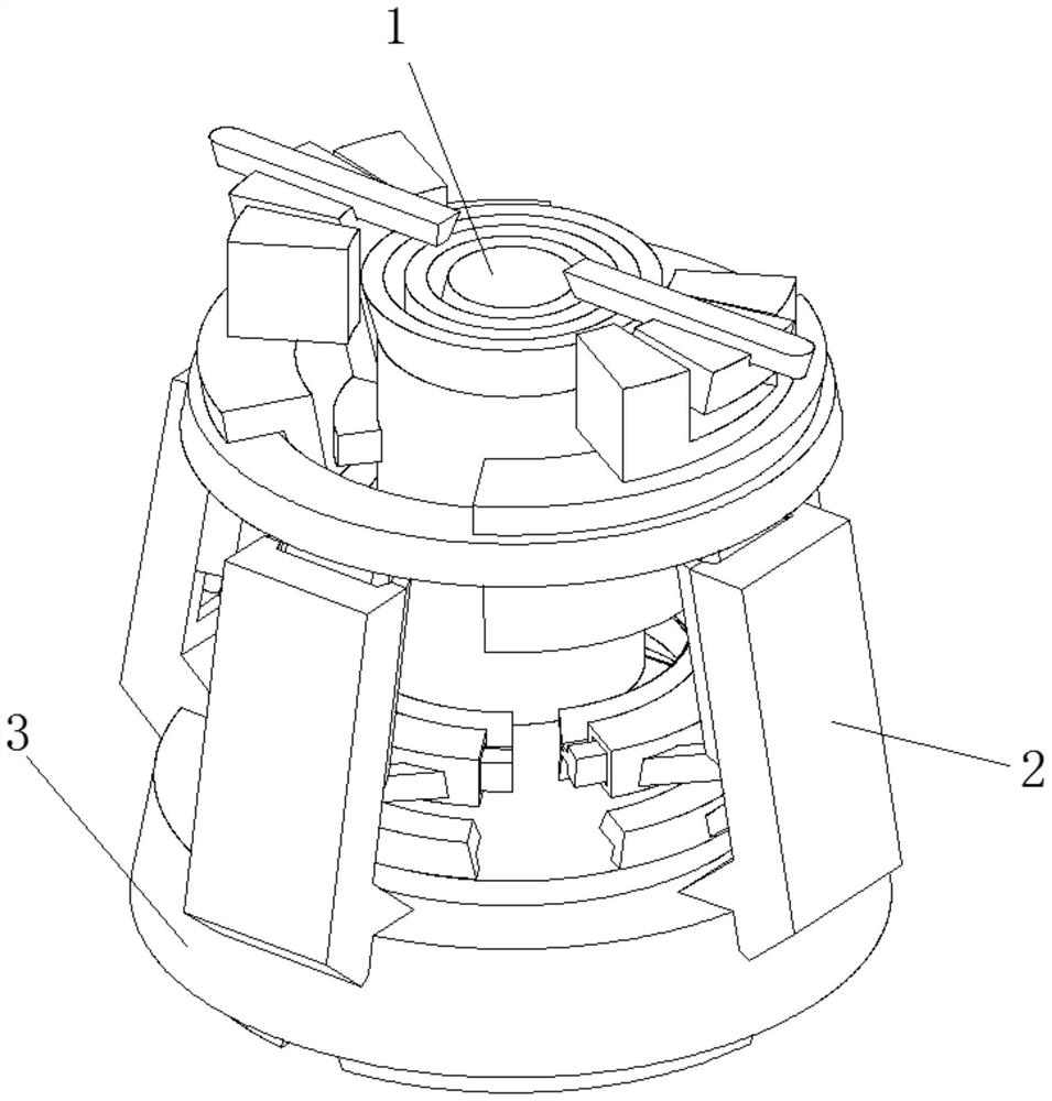
[0037] Such as Figure 1-4 As shown, the present invention provides a technical solution: a high-temperature control automatic iron ramming machine tool, including a ramming plate 3, the bottom of the ramming plate 3 is fixedly connected with a base 4, and the opening in the middle of the ramming plate 3 The hole is rotatably connected with a rotating shaft 6, and the top of the rotating shaft 6 is fixedly connected with a rotating pressing plate 5, and it is characterized in that: the side of the upper surface of the tamping plate 3 is fixedly connected with a supporting device 2, and the top of the supporting device 2 is fixed Connected with impact hammer device 1;
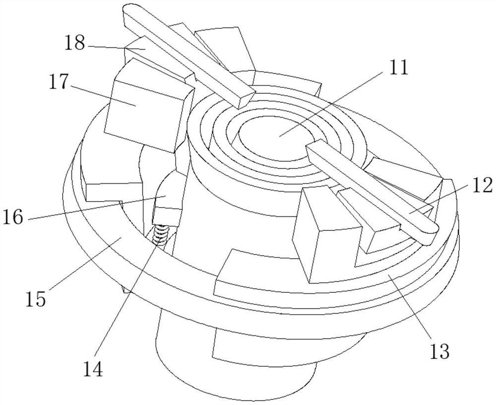
[0038] The impact hammer device 1 includes a layered rammer device 11, the upper surface of the layered rammer device 11 is provided with a control sliding shaft 12, and the control sliding shaft 12 is adapted to the layered rammer device 11, the The outer surface of the layered rammer device 11 is fixedly conn...
Embodiment 2
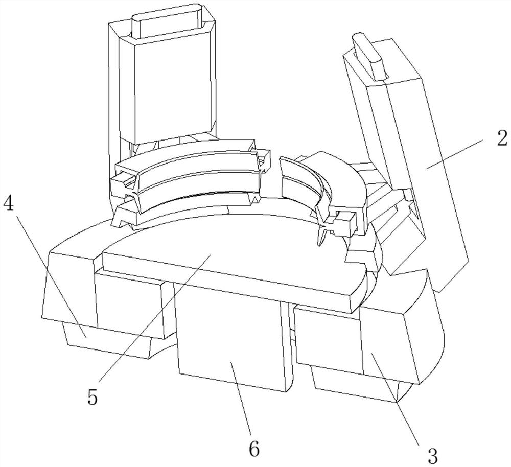
[0049] Such as Figure 5-6 As shown, on the basis of Embodiment 1, the present invention provides a technical solution: the support device 2 includes a support shaft block 21, and a through hole 22 is opened inside the support shaft block 21, and the through hole 22 A sliding rod 23 is sheathed in the inner cavity, and the top of the sliding rod 23 is fixedly connected to the lower surface of the impact hammer device 1 .
[0050] The bottom of the support shaft block 21 is fixedly connected to the top of the ramming plate 3, the side of the bottom of the slide bar 23 is fixedly connected with a bifurcated bar 24, and the end of the bifurcated bar 24 away from the slide bar 23 is fixedly connected with a surface As for the cleaning device 25 , the bottom of the sliding rod 23 is fixedly connected with a transmission rod 27 , and the bottom of the transmission rod 27 is fixedly connected with a fixing device 26 . When the top pressurized hammer hits the tamping device, the fixi...
Embodiment 3
[0057] Such as Figure 7 As shown, on the basis of Embodiment 1 and Embodiment 2, the present invention provides a technical solution: the fixing device 26 includes a fixed bottom block 261, and the upper surface of the fixed bottom block 261 is fixedly connected to the bottom of the transmission rod 27. Bottom, the bottom of the fixed bottom block 261 is provided with a material leakage groove 262, and the two sides of the material leakage groove 262 are fixedly connected with anti-fall partitions 263, and the inside of the material leakage groove 262 is provided with a falling Stone 265, the outer surface of the falling stone 265 is fixedly connected with an adsorption magnet 264. At the end of the tamping, the iron filings are attracted by the adsorption magnet 264 on the outer surface of the falling stone 265 and move sideways to reduce the impact of the falling iron filings on the overall iron quality and simultaneously achieve the cleaning effect of the iron filings.
...
PUM
 Abstract
Description
Claims
Application Information
 - Generate Ideas
- Intellectual Property
- Life Sciences
- Materials
- Tech Scout
- Unparalleled Data Quality
- Higher Quality Content
- 60% Fewer Hallucinations
Browse by: Latest US Patents, China's latest patents, Technical Efficacy Thesaurus, Application Domain, Technology Topic, Popular Technical Reports.
© 2025 PatSnap. All rights reserved.Legal|Privacy policy|Modern Slavery Act Transparency Statement|Sitemap|About US| Contact US: help@patsnap.com