
On-site monitoring system and method based on network camera

A technology for network cameras and on-site monitoring, applied in the field of cameras, can solve the problems of limited data transmission methods, inconvenient wiring, and unfavorable camera terminal structure wiring control.

Pending Publication Date: 2022-02-11
武汉云新锐信息技术有限公司
View PDF0 Cites 0 Cited by
  • Summary
  • Abstract
  • Description
  • Claims
  • Application Information

AI Technical Summary

Problems solved by technology

[0005] The purpose of the present invention is to provide a network camera-based on-site monitoring system and method to solve the problem that the existing camera itself proposed by the background technology is too complex to be connected, and the data transmission methods adopted between them are limited, which is not conducive to flexibility. According to the needs of daily use, the terminal structure of the camera is further controlled by wiring, which is likely to affect the subsequent use of the problem

Method used


Image

  • On-site monitoring system and method based on network camera
  • On-site monitoring system and method based on network camera
  • On-site monitoring system and method based on network camera

Examples


Embodiment Construction

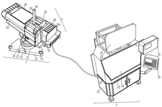
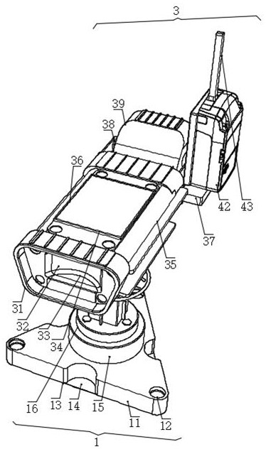
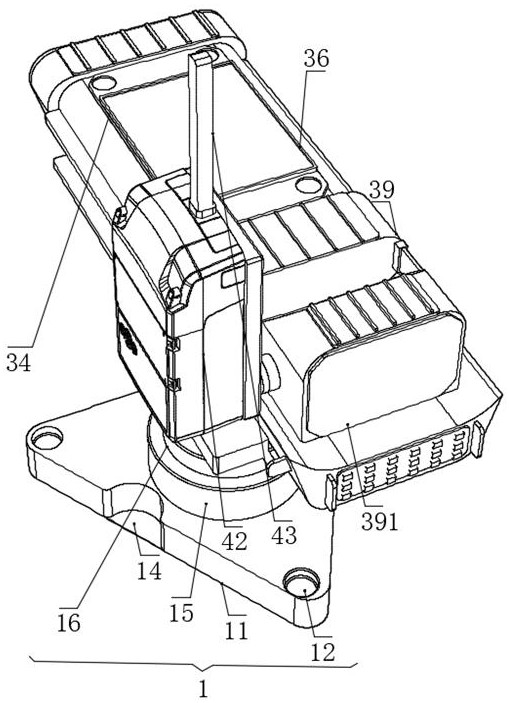
[0007] The following will clearly and completely describe the technical solutions in the embodiments of the present invention with reference to the accompanying drawings in the embodiments of the present invention. Obviously, the described embodiments are only some, not all, embodiments of the present invention. Based on the embodiments of the present invention, all other embodiments obtained by persons of ordinary skill in the art without making creative efforts belong to the protection scope of the present invention. see Figure 1-6, the present invention provides a technical solution: a network camera-based on-site monitoring system, including an on-site monitoring mechanism 1, the on-site monitoring mechanism 1 includes a first support base 11 for supporting connections, and the first support base 11 has a shape of Triangular shape, wherein the three corners of the first support base 11 are provided with circular connecting holes 12, the inner wall of the circular connecti...


PUM


Abstract

The invention discloses an on-site monitoring system and method based on a network camera, and the system comprises an on-site monitoring mechanism; the on-site monitoring mechanism comprises a first supporting base used for supporting connection, the first supporting base is in a triangular shape, and three corners of the first supporting base are respectively provided with a circular connecting hole site. Connecting threads are formed in the inner walls of the circular connecting hole sites, the ends, corresponding to the circular connecting hole sites, of the circular connecting hole sites are connected with fastening screws arranged on the lower portions of the circular connecting hole sites in a fastened mode through fastening screws, and arc-shaped open grooves are correspondingly formed in the three side edges of the first supporting base. According to the on-site monitoring system and method based on the network camera, assembling of a stepping motor and a camera recording head is facilitated through a supporting base, a circular connecting hole site and an arc-shaped open groove, a display screen control panel is conveniently assembled and installed by means of a wireless transceiver, a transceiving rod and a control mechanism, and by means of a receiving box and a wireless control table, a plurality of structures can be conveniently spliced and assembled by personnel.

Description

technical field [0001] The invention relates to the technical field of cameras, in particular to a network camera-based on-site monitoring system and method. Background technique [0002] Web camera is called WEBCAM for short, and its full name is WEB CAMERA in English. [0003] 1) Due to the temporary nature of the existing network cameras in the process of site layout, the cameras that play a monitoring role during the layout are usually installed, which usually leads to low induction and detection efficiency of the traditional cameras, and usually needs to be installed during installation. Wiring, in order to successfully establish a connection with the computer. [0004] 2) The structure of the existing camera itself is too complicated to facilitate wiring, and the data transmission methods adopted between them are limited. use. Contents of the invention [0005] The purpose of the present invention is to provide a network camera-based on-site monitoring system and ...

Claims


Application Information

Patent Timeline
IPC IPC(8): H04N7/18H04N5/225H04N5/76H04N5/232F16M11/06F16M11/18G08C17/02H04W4/30
CPCH04N7/181H04N5/76F16M11/06F16M11/18G08C17/02H04W4/30H04N23/50H04N23/66H04N23/695
Inventor 王艳
Owner 武汉云新锐信息技术有限公司
Learn More