
Hi-end electron tube amplifier circuit

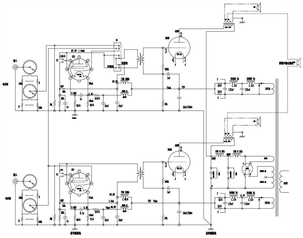
A technology of amplifier circuit and amplifier circuit, which is applied in push-pull amplifiers, phase splitters, etc., and can solve problems such as unsatisfactory sound quality, unfavorable weak signal amplification, and unsatisfactory signal transmission.

Pending Publication Date: 2021-08-31
李晓宇
View PDF0 Cites 0 Cited by
  • Summary
  • Abstract
  • Description
  • Claims
  • Application Information

AI Technical Summary

Problems solved by technology

[0002] The current electronic tube 300B single-ended amplifier uses WE310A as the driver for the front stage. Through capacitive coupling, WE310A is a side heat pipe, which is not conducive to weak signal amplification, and capacitive coupling is not ideal for signal transmission. The filament power supply of electronic tube 300B is lit with AC, which is noisy. Lighting up with ordinary rectified DC, the sound quality is still not ideal

Method used


Image

  • Hi-end electron tube amplifier circuit

Examples


Embodiment Construction

[0016] The technical solutions of the present invention will be clearly and completely described below with reference to the accompanying drawings. Obviously, the described embodiments are a part of the embodiments of the present invention, but not all of the embodiments. Based on the embodiments of the present invention, all other embodiments obtained by those of ordinary skill in the art without creative efforts shall fall within the protection scope of the present invention.

[0017] In the description of the present invention, it should be noted that the terms "center", "upper", "lower", "left", "right", "vertical", "horizontal", "inner", "outer", etc. The indicated orientation or positional relationship is based on the orientation or positional relationship shown in the accompanying drawings, which is only for the convenience of describing the present invention and simplifying the description, rather than indicating or implying that the indicated device or element must hav...


PUM


Abstract

The invention discloses a Hi-end electron tube amplifier circuit which comprises a first potentiometer, a switch switching circuit, a single-ended and push-pull conversion circuit, a first amplification circuit, a rectification follow current circuit for a filament power supply, a push-pull amplification circuit, a rectification follow current circuit, a second amplification circuit, a driving transformer, a voltage amplification circuit and a second potentiometer. The first potentiometer is electrically connected with the switch switching circuit, the switch switching circuit is electrically connected with the single-end and push-pull conversion circuit, the single-end and push-pull conversion circuit is electrically connected with the switch switching circuit, the first amplification circuit is electrically connected with the single-end and push-pull conversion circuit, and the second potentiometer is electrically connected with the voltage amplification circuit. The voltage amplifying circuit is electrically connected with the driving transformer, the driving transformer is electrically connected with the amplifying circuit II, and the filament power supply is electrically connected with the amplifying circuit I. The invention belongs to the technical field of electron tube amplifiers, and particularly relates to a Hi-end electron tube amplifier circuit.

Description

technical field [0001] The invention belongs to the technical field of electronic tube amplifiers, in particular to a Hi-end electronic tube amplifier circuit. Background technique [0002] The current electronic tube 300B single-ended amplifier uses WE310A as the driver. Through capacitive coupling, WE310A is a side heat pipe, which is not conducive to weak signal amplification, and capacitive coupling is not ideal for signal transmission. The filament power supply of electronic tube 300B is lit with AC, which is noisy. Lighting up with ordinary rectified direct current, the sound quality is still not ideal. SUMMARY OF THE INVENTION [0003] In order to solve the above problems, the present invention provides a Hi-end tube amplifier circuit with high signal-to-noise ratio and large dynamic range. [0004] In order to realize the above functions, the technical solution adopted by the present invention is as follows: a Hi-end electronic tube amplifier circuit, comprising a...

Claims


Application Information

Patent Timeline
Patent Type & Authority Applications(China)
IPC IPC(8): H03F3/28
CPCH03F3/28
Inventor 李晓宇唐少艺
Owner 李晓宇
Learn More