
Stamping device for automobile stamping part machining

A technology of automobile stamping parts and stamping devices, which is applied in the field of stamping devices for processing automobile stamping parts, and can solve problems such as failure to obtain qualified stamping parts, workpiece splashes, uneven concave-convex surfaces, etc.

Pending Publication Date: 2022-02-11
乔克
View PDF0 Cites 2 Cited by
  • Summary
  • Abstract
  • Description
  • Claims
  • Application Information

AI Technical Summary

Problems solved by technology

[0003] Compared with castings and forgings, stamping parts have the characteristics of thinness, uniformity, lightness and strength. Many parts in automobiles are stamped. There are also some problems and shortcomings in stamping process, because stamping technology relies on The extrusion force makes the workpiece have a certain shape, so when stamping, if the workpiece is not placed properly or other reasons will cause the workpiece to splash, causing injuries to personnel, and during stamping, some workpieces will fall off some debris, such as If the debris is not cleaned in time and remains on the mold, then the next time stamping, some uneven concave-convex surfaces may be left on the workpiece, and qualified stamping parts cannot be obtained

Method used


Image

  • Stamping device for automobile stamping part machining
  • Stamping device for automobile stamping part machining
  • Stamping device for automobile stamping part machining

Examples


Embodiment Construction

[0026] In order to make the technical means, creative features, goals and effects achieved by the present invention easy to understand, the present invention will be further described below in conjunction with specific embodiments.

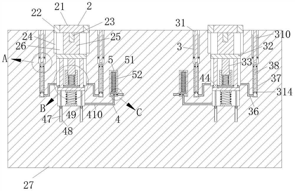
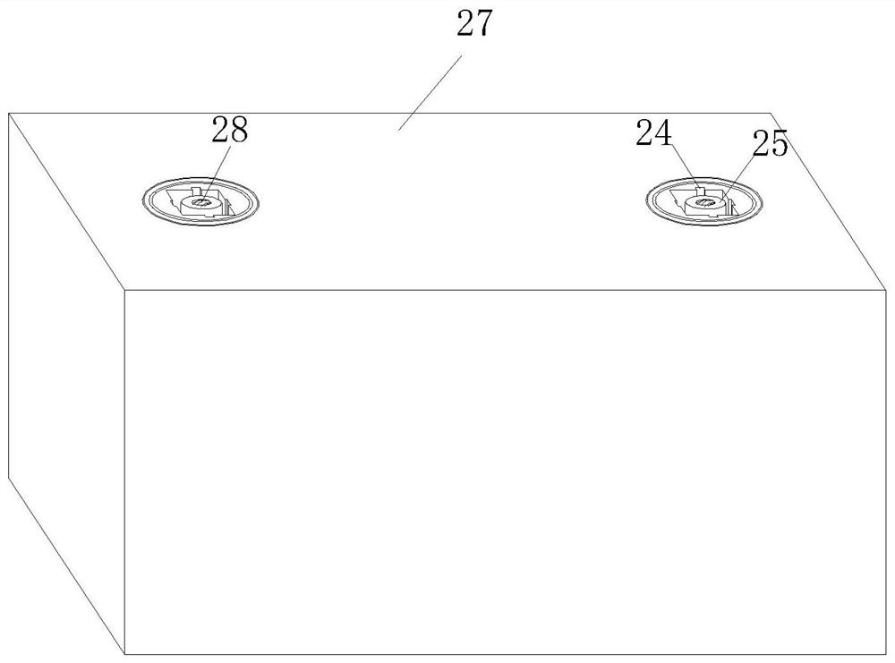
[0027] Such as Figure 1-Figure 7 As shown, a stamping device for automobile stamping parts processing according to the present invention includes a drive mechanism 1, a base mechanism 2, a protection mechanism 3, an inflation mechanism 4 and an energy storage mechanism 5, and the drive mechanism 1 has a The base mechanism 2, the outer periphery of the base mechanism 2 is fixedly connected with the protection mechanism 3, and the base mechanism 2 and the protection mechanism 3 are communicated through a first air duct 36, and the base mechanism 2. The inflatable mechanism 4 is fixedly connected to the bottom, the base mechanism 2 and the inflatable mechanism 4 are fixedly connected through a fixed rod 41, and one side of the inflatable mechanism 4...


PUM


Abstract

The invention relates to the technical field of stamping, in particular to a stamping device for automobile stamping part machining. The stamping device comprises a driving mechanism, a base mechanism, a protection mechanism, an inflation mechanism and an energy storage mechanism, wherein the base mechanism is arranged below the driving mechanism, the protection mechanism is fixedly connected to the periphery of the base mechanism, the base mechanism and the protection mechanism are communicated through a first air guide pipe, the lower portion of the base mechanism is fixedly connected with the inflation mechanism, one side of the inflation mechanism is fixedly connected with the energy storage mechanism, and the inflation mechanism and the energy storage mechanism are connected through a second air guide pipe; and the driving mechanism can drive left and right stamping rods to fall alternately, the base mechanism can replace a proper stamping die, the protection mechanism can automatically rise during stamping to prevent a workpiece from jumping and hurting people during stamping, the inflation mechanism can inflate enough gas into the energy storage mechanism, the energy storage mechanism can release the gas instantly, and chippings in the die are blown away through an air spraying head.

Description

technical field [0001] The invention relates to the technical field of stamping, in particular to a stamping device used for processing automobile stamping parts. Background technique [0002] Stamping is a production technology that uses the power of conventional or special stamping equipment to directly subject the sheet to deformation force and deform in the mold, so as to obtain product parts of a certain shape, size and performance. [0003] Compared with castings and forgings, stamping parts have the characteristics of thinness, uniformity, lightness and strength. Many parts in automobiles are stamped. There are also some problems and shortcomings in stamping process, because stamping technology relies on The extrusion force makes the workpiece have a certain shape, so when stamping, if the workpiece is not placed properly or other reasons will cause the workpiece to splash, causing injuries to personnel, and during stamping, some workpieces will fall off some debris, ...

Claims


Application Information

Patent Timeline
Patent Type & Authority Applications(China)
IPC IPC(8): B21D22/02B21D37/14B21D55/00B08B5/02
CPCB21D22/02B21D37/14B21D55/00B08B5/02
Inventor 乔克许聪
Owner 乔克
Learn More