
Automated monitoring and control of safety in a production area

a production area and automatic monitoring technology, applied in the field of automatic monitoring and control of safety in the production area, can solve the problems of non-safe work practices, high cost of injury to persons and property in the workplace, and manual monitoring of employees, vendors, visitors through close circuit camera or direct supervision, so as to avoid damage to the tool, the vehicle, the article in progress or the machin

Active Publication Date: 2012-06-14
SEALED AIR U S
View PDF36 Cites 143 Cited by
  • Summary
  • Abstract
  • Description
  • Claims
  • Application Information

AI Technical Summary

Benefits of technology

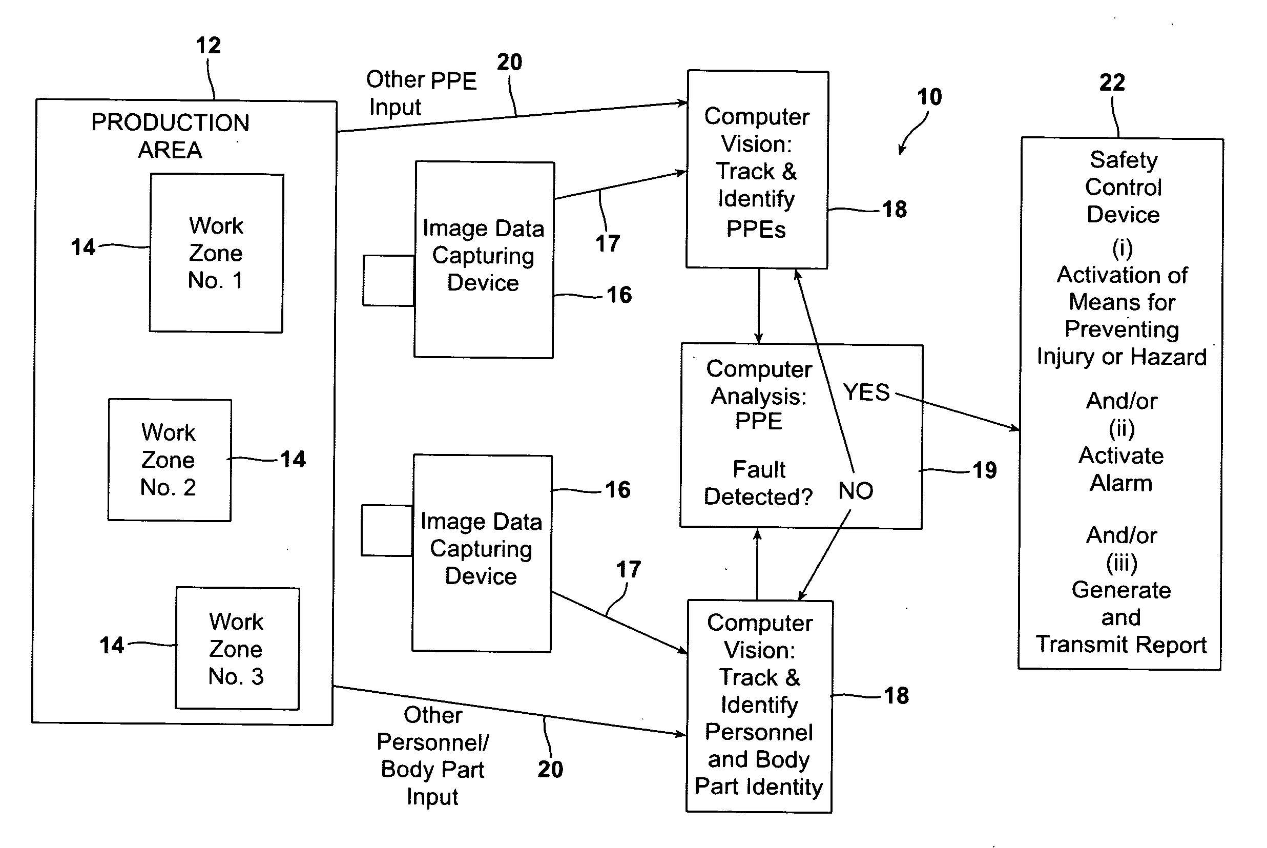
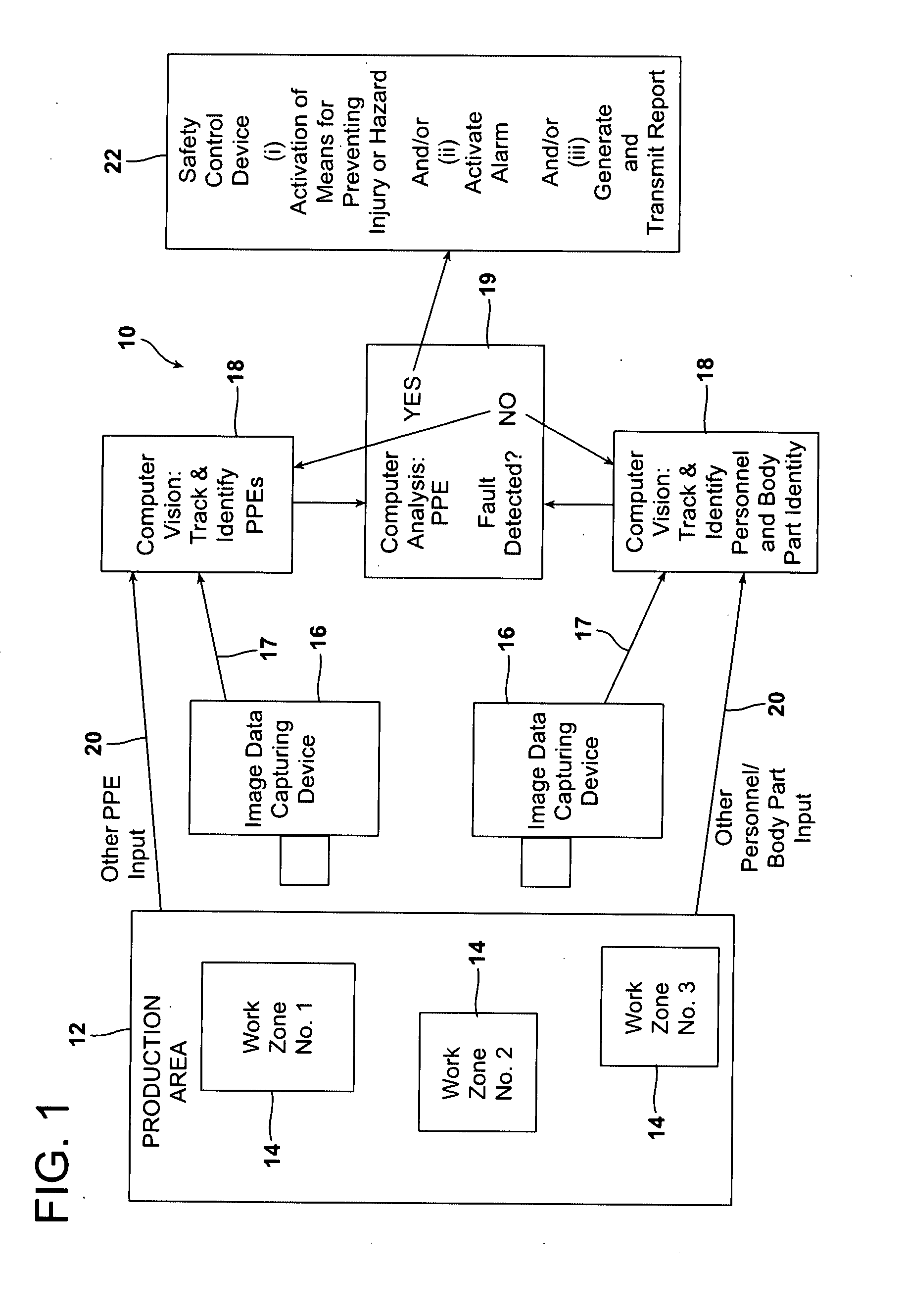
The patent describes an automated system for monitoring and controlling safe working practices in a production area. The system uses image data to capture the area and process it to identify and track individuals and equipment. If any issues are detected, the system can activate safety controls, such as alarms or shutting down equipment, to prevent accidents and improve safety. The system can also generate a report with the image data and the time it was captured. Overall, the system helps to create a safer workplace and prevent accidents.

Problems solved by technology

Many of these accidents can be attributable to safety violations and non-safe work practices.
Although there are numerous vendors supplying the market with personal protective equipment (hereinafter, “PPE”) such as safety glasses and safety shoes, and although employers require employees to conduct periodic safety meetings, the cost of injury to persons and property in the workplace remains high.
Manual monitoring of employees, vendors, and visitors through close circuit camera or direct supervision is both expensive and subjective.
The overall reporting of violations can be inaccurate and unverifiable.

Method used


Image

  • Automated monitoring and control of safety in a production area
  • Automated monitoring and control of safety in a production area
  • Automated monitoring and control of safety in a production area

Examples


examples

[0136]As an example, a cutting board is located at a sandwich making station. The sandwich-maker is located at the cutting board and is monitored by a video camera such as a Trendnet® TV IP110 interne camera server network camera, available from RitzCamera.com. The camera sends a visual data wirelessly via a router (e.g., NETGEAR®—RangeMax 802.11g Wireless Router, model WPN824, available from Best Buy, P.O. Box 9312, Minneapolis, Minn. 55440) to a computer (e.g., eMachines—Netbook with Intel® Atom™ Processor, Model: EM250-1915, also available from Best Buy). The computer processes the data in a near real time manner to determine if the sandwich-maker is complying with proper safety protocol in using a knife at the cutting board. The output signal from the computer controls light emitting diodes embedded within the cutting board in the event that the use of the knife is determine to be outside of a safe movement range programmed into the computer. The cutting board, made with food-gr...


PUM


Abstract

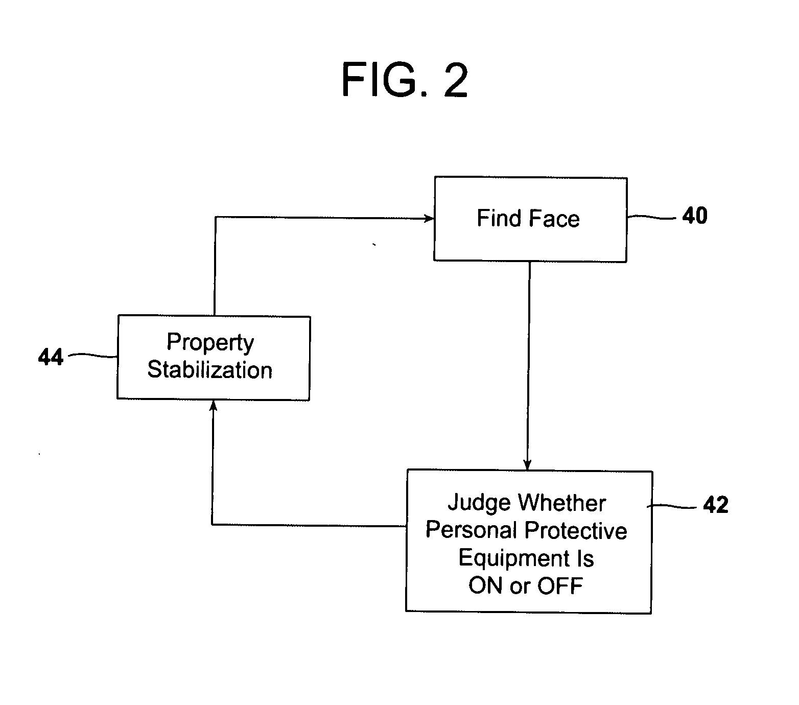
A machine vision process monitors and controls safe working practice in a production area by capturing and processing image data relative to personal protective equipment (PPE) worn by individuals, movement of various articles, and movement-related conformations of individuals and other objects in the production area. The data is analyzed to determine whether there is a violation of a predetermined minimum threshold image, movement, or conformation value for a predetermined threshold period of time. The determination of a safety violation triggers computer activation of a safety control device. The process is carried out using a system including an image data capturing device, a computer and computer-readable program code, and a safety control device.

Description

[0001]This application claims the benefit of, and incorporates by reference the entirety of, Provisional Application No. 61 / 134,654 filed on Apr. 1, 2010FIELD OF THE INVENTION[0002]The invention is directed to automated monitoring and control of safety in a production area.BACKGROUND OF THE INVENTION[0003]In 2007, worker compensation claims tallied a total of over 80 billion dollars in the United States. Accidents associated with back injuries accounted for one in every five claims and liability associated with damaged eyes totaled over $100 million dollars. There were four million non-fatal workplace injuries in 2007 and over 5000 workplace deaths. Many of these accidents can be attributable to safety violations and non-safe work practices.[0004]Although there are numerous vendors supplying the market with personal protective equipment (hereinafter, “PPE”) such as safety glasses and safety shoes, and although employers require employees to conduct periodic safety meetings, the cost...

Claims


Application Information

Patent Timeline
Patent Type & Authority Applications(United States)
IPC IPC(8): G08B21/00H04Q5/22G06K9/00H04N9/03
CPCG08B21/12G08B21/24H04Q9/02G06K9/00228H04Q2209/845G06K9/00362G06K9/00771H04Q2209/47G06K9/00281G06Q10/08G06V40/171G06V40/161G06V40/10G06V20/52H04N3/38H04W64/00H04N9/03
Inventor DE LUCA, NICHOLASSATO, KOICHI
Owner SEALED AIR U S
Learn More