
Battery management circuit, battery management system, electric vehicle and battery management method

A technology of battery management circuit and battery unit, which is applied in the field of electric vehicle and battery management, and battery management circuit. It can solve problems such as sparks generated by connector contacts, failure to start smoothly, and sparks generated by battery contacts, so as to avoid overheating of components and perfect Battery hot-swapping solution, avoiding the effect of charging and discharging between batteries

Pending Publication Date: 2022-02-08
马力达科技(南京)股份有限公司
View PDF0 Cites 2 Cited by
  • Summary
  • Abstract
  • Description
  • Claims
  • Application Information

AI Technical Summary

Problems solved by technology

However, on the one hand, in the high-current application scenarios of electric vehicles, such a solution will cause high heat generation of circuit components and poor efficiency; on the other hand, when the input terminal of the power consumption system has a large input capacitance, the The battery is connected by plugging and unplugging. When the battery is connected, a large pulse current will be generated at the moment
This pulse current time is usually within one millisecond, but the current may be as high as hundreds of amperes, which will easily cause the over-current protection of the battery management system (BMS) to activate the load and fail to start smoothly; in addition, it will also be caused by this pulse Electrical current causes sparks at connector contacts
However, the current solution cannot solve the problem of sparks at the battery contacts due to instantaneous high current when the battery is hot-swapped.

Method used


Image

  • Battery management circuit, battery management system, electric vehicle and battery management method
  • Battery management circuit, battery management system, electric vehicle and battery management method
  • Battery management circuit, battery management system, electric vehicle and battery management method

Examples


Embodiment Construction

[0021] The implementation of the present application is described below through specific examples, and those skilled in the art can easily understand other advantages and effects of the present application from the information disclosed in the present application. The present application can also be implemented or applied in different specific implementation modes, and the details in the present application can also be modified or changed according to different viewpoints and application systems without departing from the spirit of the present application. It should be noted that, in the case of no conflict, the embodiments in the present application and the features in the embodiments can be combined with each other.

[0022] The embodiments of the present application will be described in detail below with reference to the accompanying drawings, so that those skilled in the art of the present application can easily implement them. The present application can be embodied in va...


PUM


Abstract

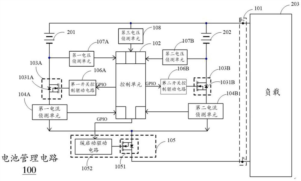
The embodiment of the invention discloses a battery management circuit, a battery management system, an electric vehicle and a battery management method. The battery management circuit comprises a power supply interface, a plurality of branches and a control unit. The battery interface in each branch is coupled with a battery unit, and the cathode connecting end of the battery interface is coupled and grounded through a branch switch unit and a current detection unit. Each branch switch unit comprises a switch element used for switching on / off the branch and a diode with the conduction direction pointing to the negative electrode connecting end of a battery. The control unit drives the branch switch units to be conducted to form a second conductive path replacing a first conductive path or disconnect the second conductive path according to whether the changes of the current values in the branches reach a threshold, so that the elements are prevented from being overheated. When there is a voltage difference between the batteries, the diodes in the branches with lower voltages are cut off by a reverse bias voltage, so that charging and discharging between the batteries are avoided. In addition, a slow-start main switch unit can avoid spark generation caused by sudden current change. A perfect battery hot plug scheme is realized.

Description

technical field [0001] The present application relates to the technical field of battery management, in particular to a battery management circuit, a battery management system, an electric vehicle and a battery management method. Background technique [0002] At present, the application of electric vehicles is becoming more and more extensive. Many electric vehicles adopt the technical solution of multiple batteries connected in parallel for power supply. How to realize hot-swapping when replacing batteries has become an urgent problem to be solved. [0003] When multiple battery modules are directly connected in parallel, it is necessary to ensure that the voltages between the batteries are very close, otherwise there will be problems such as instantaneous discharge causing battery overheating, mutual charge and discharge between batteries, etc., which may easily cause the battery to overheat and catch fire. Therefore, it is not possible to directly and simply connect multi...

Claims


Application Information

Patent Timeline
Patent Type & Authority Applications(China)
IPC IPC(8): H02J7/00B60L58/18B60L3/00B60L3/04H01M10/42H01M10/44
CPCH02J7/0013H02J7/0029H02J7/0031H02J7/00304H02J7/00309H02J7/0063B60L58/18B60L3/0046B60L3/04H01M10/4207H01M10/441H01M10/425H01M2220/20H01M2010/4271Y02E60/10Y02T10/70
Inventor 马斌严
Owner 马力达科技(南京)股份有限公司
Learn More