
Integrated power distribution device installation frame and integrated power distribution device

A power distribution device and installation frame technology, applied in substation/power distribution device casing, circuit device, substation/switchgear board/panel/desk, etc., can solve the problem of difficulty in meeting miniaturization requirements, complex side-by-side wiring, and mutual interference and other problems to achieve the effect of avoiding detection interference, compact arrangement and saving space

Pending Publication Date: 2022-02-08
EAST GRP CO LTD
View PDF1 Cites 4 Cited by
  • Summary
  • Abstract
  • Description
  • Claims
  • Application Information

AI Technical Summary

Problems solved by technology

Referring to CN200910075274, a UPS integrated power distribution system is disclosed, including several mains input and output interfaces, UPS input and output ports, lightning protection module, switching module, data monitoring module, current sensor, power supply module, etc., especially several current sensors If the arrangement is relatively tight, it is easy to cause mutual interference during detection. If the arrangement is relatively far away, it will waste space and make wiring complicated
Therefore, the power distribution system in CN200910075274 is made very large, the cost is high and it is difficult to meet the current miniaturization requirements

Method used


Image

  • Integrated power distribution device installation frame and integrated power distribution device
  • Integrated power distribution device installation frame and integrated power distribution device
  • Integrated power distribution device installation frame and integrated power distribution device

Examples


Embodiment Construction

[0037] In order to describe the technical content, structural features, achieved goals and effects of the present invention in detail, the following will be described in detail in conjunction with the embodiments and accompanying drawings.

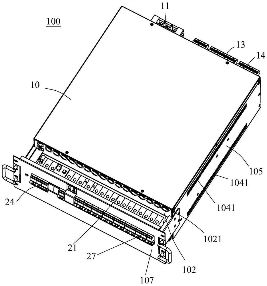
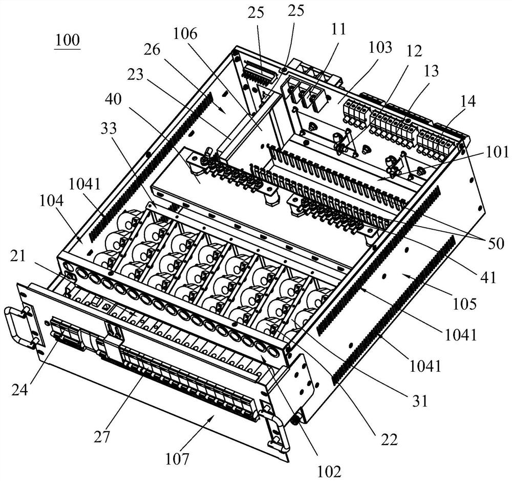
[0038] refer to Figure 1 to Figure 6 , the present invention discloses an integrated power distribution device 100, comprising a housing 10 with an installation cavity 101, input interfaces (11, 12) installed on the housing 10, several output interfaces (13, 14), installed on the The circuit board (not shown in the figure) in the installation cavity 101, the input interface (11, 12) and the output interface (13, 14) are connected to form a number of power distribution circuits, each of the power distribution circuits An air switch 21 for controlling the on-off of the power distribution circuit and a current sensor 22 for detecting the current of the power distribution circuit are installed on it, and the circuit board controls the operati...


PUM


Abstract

The invention discloses an integrated power distribution device installation frame which comprises a shell with an installation cavity, a plurality of installation plates are fixed in the installation cavity in the left-right direction, each installation plate is arranged in the front-back direction of the installation cavity, and an installation area for installing a current sensor is formed between every two adjacent installation plates or between the installation plate and a side plate of the shell. At least one installation area is internally provided with a plurality of mounting structures for mounting the current sensors, the plurality of mounting structures are arranged in the front-back direction of the mounting cavity and are different in height, the current sensors can be obliquely mounted on the mounting plate, so that the detection holes of the current sensors are obliquely upward, and the heights of the plurality of current sensors in the installation areas are different. Compared with the prior art, the device is used in multiple power distribution loops and a power distribution device which is provided with multiple current sensors to detect the current of each power distribution loop, so that space is saved, arrangement is compact, the final size of the power distribution device is small, and mutual interference among the multiple power distribution loops is avoided. The invention also discloses a corresponding integrated power distribution device.

Description

technical field [0001] The invention relates to the field of power distribution, in particular to an integrated power distribution device. Background technique [0002] A power distribution device, especially a USP power distribution device, generally has several power distribution circuits. For power distribution safety, a current sensor is installed on each power distribution circuit. Referring to CN200910075274, a UPS integrated power distribution system is disclosed, including several mains input and output interfaces, UPS input and output ports, lightning protection module, switching module, data monitoring module, current sensor, power supply module, etc., especially several current sensors If the arrangement is relatively tight, it is easy to cause mutual interference during detection. If the arrangement is relatively far away, it will waste space and make wiring complicated. Therefore, the power distribution system in CN200910075274 is made very large, the cost is h...

Claims


Application Information

Patent Timeline
Patent Type & Authority Applications(China)
IPC IPC(8): H02B1/26H02B1/04H02B1/01H02B1/20H02J9/06
CPCH02B1/26H02B1/04H02B1/01H02B1/202H02J9/06
Inventor 冯强龚功春
Owner EAST GRP CO LTD
Learn More