Miniature environment-resistant circular electric connector

An electrical connector and environment-resistant technology, which is applied in the direction of connection, two-part connection device, and parts of the connection device, can solve the problem that small electrical connectors cannot meet the rated current and external dimensions at the same time, and achieve high rated current, Good sealing performance and small size

Pending Publication Date: 2022-02-08
厦门鼎芯科技有限公司
View PDF0 Cites 0 Cited by
  • Summary
  • Abstract
  • Description
  • Claims
  • Application Information

AI Technical Summary

Problems solved by technology

[0004] The purpose of the present invention is to provide a small environment-resistant circular electrical connector, which aims to solve the problem that the existing small electrical connectors cannot meet the conditions of rated current and external dimensions at the same time

Method used


Image

  • Miniature environment-resistant circular electric connector
  • Miniature environment-resistant circular electric connector
  • Miniature environment-resistant circular electric connector

Examples


Embodiment 1

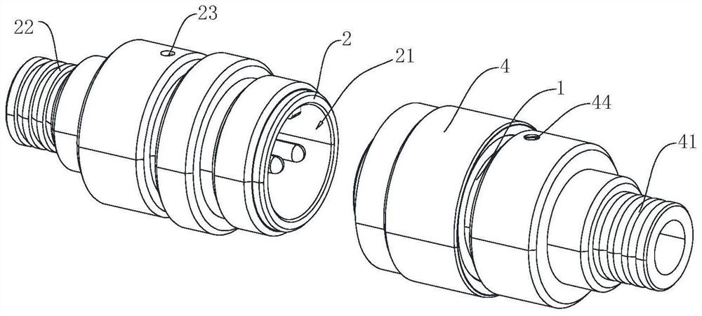
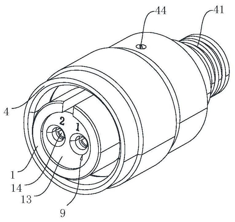
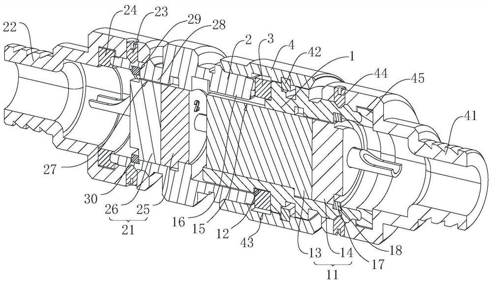
[0034] combine figure 1 and figure 2 , a small environment-resistant circular electrical connector, including a socket and a plug used in conjunction with the socket, the plug includes a first shell 1 and a plug body 11 disposed inside the first shell 1, and the socket includes a second shell 2 And the socket body 21 arranged inside the second housing 2; wherein, it also includes a sealing structure for sealing the gap between the first housing 1 and the second housing 2, and the outer wall of the first housing 1 is provided with a first ring The locking groove 12 , the sealing structure includes a first annular sealing gasket 3 disposed in the first annular locking groove 12 , and the front end of the second housing 2 is in contact with the outside of the first annular sealing gasket 3 .

[0035] Specifically, both the first housing 1 and the second housing 2 are hollow, the plug body 11 is installed in the first housing 1, and the socket body 21 is installed in the second ...

Embodiment 2

[0045] combine Figure 4 , in this embodiment, the outer side of the first annular gasket 3 is provided with a first relief groove 5 for the front end of the second housing 2 to be embedded in, and the sealing structure also includes a fourth groove fixed at the front end of the second housing 2 . Annular gasket 51, a wedge-shaped block 52 fixed on the front end of the first housing 1, the wedge-shaped block 52 is arranged in a ring shape, and one end extends into the first relief groove 5, and the fourth annular gasket 51 is provided with a wedge-shaped block 52 The second relief groove 53 is embedded, and the fourth annular gasket 51 is pressed against the first relief groove 5 after the wedge-shaped block 52 is inserted into the second relief groove 53 .

[0046] During installation, the fourth annular gasket 51 is pre-installed on the front end of the second housing 2. It should be noted that the front end of the second housing 2, that is, the end of the second housing 2 f...


PUM


Abstract

The embodiment of the invention discloses a miniature environment-resistant circular electric connector, which comprises a socket and a plug matched with the socket for use, and is characterized in that the plug comprises a first shell and a plug body arranged in the first shell, and the socket comprises a second shell and a socket body arranged in the second shell; wherein the electric connector includes a sealing structure which is used for sealing a gap at the joint of the first shell and the second shell, a first annular clamping groove is formed in the outer wall of the first shell, the sealing structure comprises a first annular sealing gasket arranged in the first annular clamping groove, and the front end of the second shell abuts against the outer side of the first annular sealing gasket. According to the electric connector, the first annular sealing gasket plays a role in sealing the joint of the first shell and the second shell, so that the electric connector is good in sealing performance, and meanwhile, the electric connector is small in size and large in rated current, has moisture-proof, salt-mist-proof and waterproof performance, and meets market requirements.

Description

technical field [0001] The invention relates to the field of electrical connectors, in particular to a small environment-resistant circular electrical connector. Background technique [0002] At present, in the fields of ships and other fields, due to the limitation of equipment space, etc., connectors with small dimensions (the size of the connectors after docking is less than Φ16.5mm×55mm) and can transmit large currents are required. And the connector needs to have good moisture resistance, salt spray resistance and certain sealing and waterproof performance. The small environment-resistant connector can meet the requirements of the use space while ensuring that the equipment still has reliable and stable performance in harsh environments. [0003] Some of the existing connectors on the market can meet the requirements in size and performance, but the transmittable current is too small (below 5A), and the sealing performance and rated current of some connectors can meet ...

Claims


Application Information

Patent Timeline
Patent Type & Authority Applications(China)
IPC IPC(8): H01R13/52H01R13/533H01R13/04H01R13/10H01R24/00
CPCH01R13/5202H01R13/533H01R13/04H01R13/10H01R24/00
Inventor 鄢京王美男孙佳
Owner 厦门鼎芯科技有限公司
Why Eureka
Try Eureka