Power battery and vehicle

A technology for power batteries and battery boxes, which is applied in the direction of batteries, battery pack components, circuits, etc., can solve the problems of reduced high temperature resistance, uncontrollable, and straight rise of battery system temperature, so as to reduce the speed of spread and improve safety performance Effect

Pending Publication Date: 2022-02-01
北京胜能能源科技有限公司
View PDF0 Cites 0 Cited by
  • Summary
  • Abstract
  • Description
  • Claims
  • Application Information

AI Technical Summary

Problems solved by technology

[0002] The power battery is the core component of the vehicle, but as the energy density of the battery cell in the battery system increases, the risk of thermal runaway of the battery cell increases. When the thermal runaway of the battery cell reaches a certain temperature, an uncontrollable state will appear , causing the temperature inside the battery system to rise sharply, causing combustion and explosion
[0003] Even if the vehicle is usually equipped with a battery thermal management system to dissipate heat and cool down the battery cell, it cannot completely prevent the thermal runaway of the battery cell. After the thermal runaway of the battery cell occurs locally, it will quickly spread to the entire battery system
The upper cover of the battery box usually adopts a lightweight design, or is made of plastic or thin-walled stamped metal, which reduces the high temperature resistance of the battery box cover toward the passenger compartment. Once thermal runaway occurs, toxic and high-temperature gas or flames will quickly Break through the shell of the battery box and spread to the crew compartment, reducing the survival chance of the crew members

Method used


Image

  • Power battery and vehicle
  • Power battery and vehicle
  • Power battery and vehicle

Examples


Embodiment Construction

[0029] In order to make the technical problems solved by the present invention, the technical solutions adopted and the technical effects achieved clearer, the technical solutions of the present invention will be further described below in conjunction with the accompanying drawings and through specific implementation methods. It should be understood that the specific embodiments described here are only used to explain the present invention, but not to limit the present invention. In addition, it should be noted that, for the convenience of description, only the parts related to the present invention are shown in the drawings but not all of them.

[0030] In the description of the present invention, unless otherwise clearly specified and limited, the terms "connected", "connected" and "fixed" should be understood in a broad sense, for example, it can be a fixed connection, a detachable connection, or an integrated ; It can be a mechanical connection or an electrical connection;...


PUM


Abstract

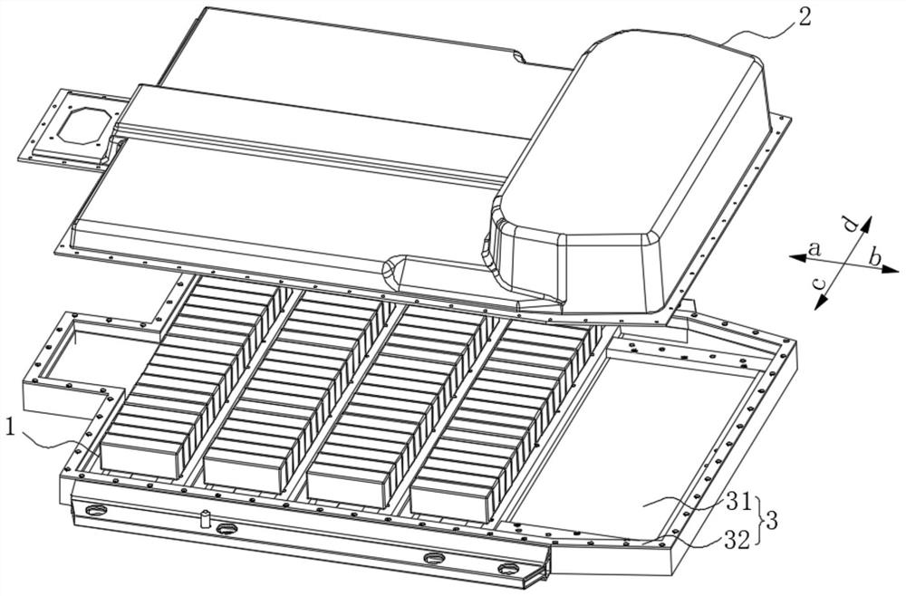
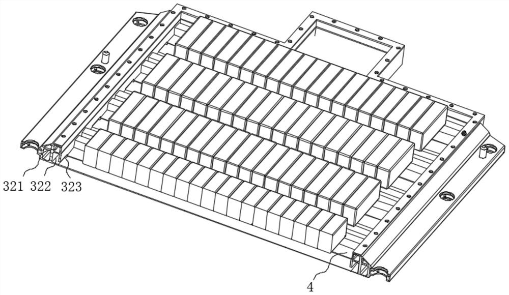
The invention relates to the technical field of batteries, and discloses a power battery which comprises a battery cell and a battery box, the battery box is provided with an accommodating cavity, the battery box comprises a lower box body and an upper box body, the upper box body covers the lower box body, and the battery cell is fixed on the lower box body so as to be positioned in the accommodating cavity. A first pressure relief channel and a second pressure relief channel which are communicated with each other are arranged on the lower box body, the lower box body comprises a bottom plate and a side beam arranged in the circumferential direction of the bottom plate, the first pressure relief channel is arranged on the bottom plate, the second pressure relief channel is arranged in the side beam and can be communicated with the outside, the battery cell is arranged on the bottom plate, and the pressure relief valve is arranged towards the first pressure relief channel. When thermal runaway of the battery cell occurs, harmful substances can be directly sprayed into the first pressure relief channel and discharged out of the battery box through the second pressure relief channel, so that the spreading speed of thermal diffusion in the battery box is reduced, and the safety performance of the battery system is improved. The invention further discloses a vehicle which comprises the power battery, and harmful substances can be discharged in time when the battery cell is in thermal runaway.

Description

technical field [0001] The invention relates to the technical field of batteries, in particular to a power battery and a vehicle. Background technique [0002] The power battery is the core component of the vehicle, but as the energy density of the battery cell in the battery system increases, the risk of thermal runaway of the battery cell increases. When the thermal runaway of the battery cell reaches a certain temperature, an uncontrollable state will appear , causing the temperature inside the battery system to rise sharply, causing combustion and explosion. [0003] Even though the vehicle usually installs a battery thermal management system to dissipate heat and cool down the battery cell, it cannot completely prevent the thermal runaway of the battery cell. After a local thermal runaway occurs in the battery cell, it will quickly spread to the entire battery system. The upper cover of the battery box usually adopts a lightweight design, or is made of plastic or thin-...

Claims


Application Information

Patent Timeline
IPC IPC(8): H01M50/367H01M50/383H01M50/249H01M50/244H01M50/209
CPCH01M50/367H01M50/383H01M50/249H01M50/244H01M50/209H01M2220/20Y02E60/10
Inventor 李鑫李玉军侯艳丽李鸿键
Owner 北京胜能能源科技有限公司
Why Eureka
Try Eureka