Eureka AIR delivers breakthrough ideas for toughest innovation challenges, trusted by R&D personnel around the world.

Unmanned chariot control system time trigger bus

A time-triggered and control system technology, applied in the field of information bus, which can solve the problems of multiple redundancy and high fault tolerance, unable to meet the bus time determinism, reducing the survival rate of the battlefield, etc., and achieve the effect of low delay and jitter

Pending Publication Date: 2022-02-01
江苏清盐智能科技有限公司
View PDF0 Cites 2 Cited by
  • Summary
  • Abstract
  • Description
  • Claims
  • Application Information

AI Technical Summary

Problems solved by technology

[0003] The unmanned chariot control system is an important part of the unmanned chariot. The data bus architecture adopted directly determines the performance of the unmanned chariot. In particular, the current unmanned chariot control system uses a distributed integrated modular electronic system. The traditional control system architecture bus cannot meet the requirements of bus time determinism, multi-redundancy, high fault tolerance, combinability, inheritability, and high bandwidth, which restricts the performance of the fire control system of the turret and weapon station, thereby reducing the battlefield survival rate

Method used


Image

  • Unmanned chariot control system time trigger bus
  • Unmanned chariot control system time trigger bus
  • Unmanned chariot control system time trigger bus

Examples


Embodiment Construction

[0018] The technical invention will be further described below using the accompanying drawings and embodiments. The accompanying drawings described here are used to provide a further understanding of the technical invention, constitute a part of the application, and do not constitute a limitation to the technical invention.

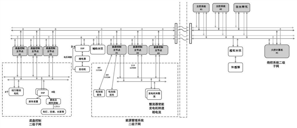
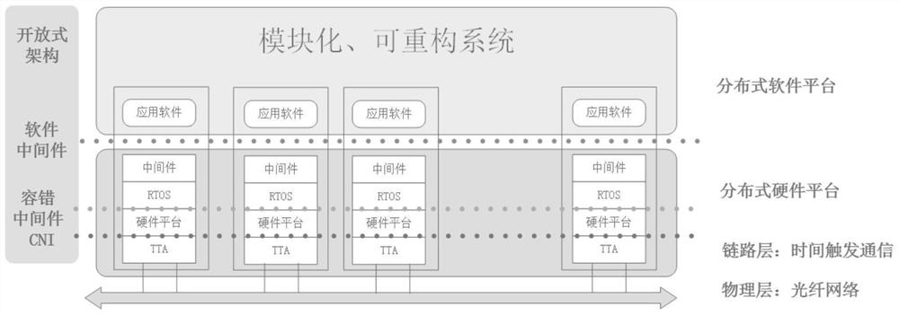
[0019] The time-triggered bus of the unmanned combat vehicle control system adopts distributed communication link technology, and uses the dual-redundancy time-triggered bus switching network to realize the communication between the chassis control system, energy control system, perception system, gun control system, auxiliary system, etc., and the main controller. And communication between autonomous units to ensure real-time and reliability of the system. The control system of the unmanned combat vehicle is divided into several functional blocks according to the functions. The system architecture inside each functional block is built by the functional co...


PUM


Abstract

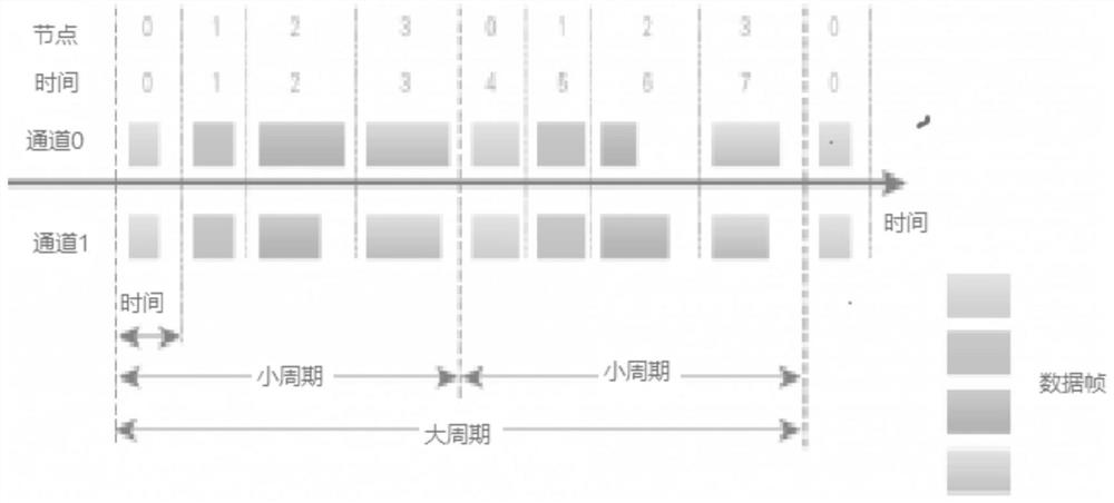
The invention provides an unmanned combat vehicle control system time trigger bus. According to the system, a fault-tolerant protocol based on time triggering is adopted, and redundant nodes and redundant functions are supported to be implemented on a plurality of nodes. The operation of the communication control chip is based on a time reference established by a fault-tolerant high-precision global clock, wherein the bus communication control hardware comprises bus monitoring. When a failure node appears in the system, normal communication of other nodes is not influenced. The main control system adopts a dual-redundancy design, control tasks are completely undertaken by a normal main control system when one of the main control systems fails, chassis control and energy control adopt a multi-redundancy and multi-node design, and the problem that the unmanned vehicle cannot run due to a single failure is avoided. The time-triggered bus adopts a dual-redundancy design to improve the reliability. The calculation task of the autonomous unit is undertaken by an independent controller, and the bus further comprises a sensing system, a gun control system, an auxiliary system and the like. The unmanned chariot control system time trigger bus can meet the technical characteristics of high data volume, high real-time performance and the like of a new generation unmanned chariot control system bus.

Description

[0001] Technical field [0002] The technical invention relates to the field of information bus technology, in particular to a time-triggered bus of an unmanned chariot control system. Background technique [0003] The unmanned chariot control system is an important part of the unmanned chariot. The data bus architecture adopted directly determines the performance of the unmanned chariot. In particular, the current unmanned chariot control system uses a distributed integrated modular electronic system. The traditional control system architecture bus cannot meet the requirements of bus time determinism, multi-redundancy, high fault tolerance, combinability, inheritability, and high bandwidth, which restricts the performance of the fire control system of the turret and weapon station, thereby reducing the battlefield survival rate. In particular, the future unmanned combat vehicle bus must have more functions, better adaptability, higher reliability and stronger survivability. ...

Claims


Application Information

Patent Timeline
Patent Type & Authority Applications(China)
IPC IPC(8): G05B9/03
CPCG05B9/03
Inventor 孙磊
Owner 江苏清盐智能科技有限公司
Why Eureka
Eureka Blog
Learn More