Punching device and punching method

A punching device and punching technology, which is applied in the fields of drilling and flushing, and punching devices, can solve problems such as the collapse of the cutting surface ore layer, and achieve the effect of improving the punching effect and avoiding impact

Pending Publication Date: 2022-02-01
BEIJING RESEARCH INSTITUTE OF CHEMICAL ENGINEERING AND METALLURGY
View PDF0 Cites 0 Cited by
  • Summary
  • Abstract
  • Description
  • Claims
  • Application Information

AI Technical Summary

Problems solved by technology

[0004] The purpose of the present invention is to provide a punching device and a punching method, which can avoid the impact of water flow on the cutting surface (formed by cutting the ore layer section) as far as possible when punching, so as to solve the problem of the collapse of the cutting surface ore layer caused by excessive punching

Method used


Image

  • Punching device and punching method
  • Punching device and punching method
  • Punching device and punching method

Examples


Embodiment 1

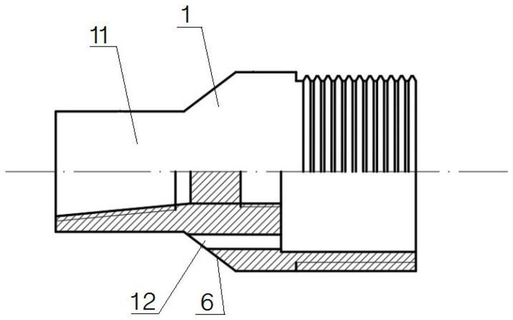
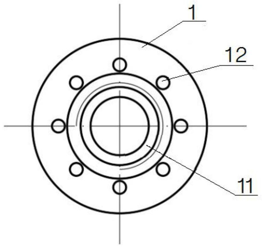
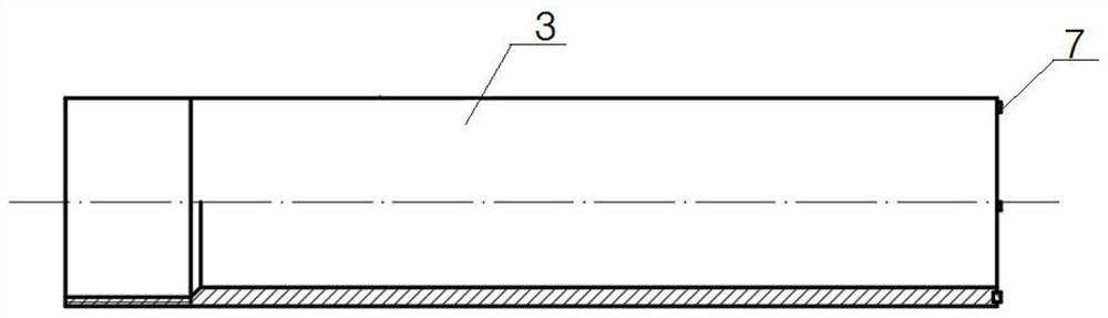
[0053] Such as Figure 1-6As shown, this embodiment provides a punching device 100, specifically a punching device that can satisfy the secondary well-forming process of cutting and constructing filters. It mainly includes an adapter 1, a flushing pipe 2 and an outer Protective tube 3. The adapter 1 is provided with a liquid inlet flow channel 11 and a liquid outlet flow channel 12, and the liquid inlet flow channel 11 and the liquid outlet flow channel 12 are arranged at intervals; one end of the adapter 1 is used to connect with the lowering part. The flushing pipe 2 is connected with the other end of the adapter 1, so as to introduce the punching liquid in the liquid inlet channel 11 into the borehole to be flushed, and perform punching. The outer protective tube 3 is connected to the other end of the adapter 1, and the outer protective tube 3 is sleeved on the outer periphery of the flushing tube 2, and an annular liquid outlet cavity 4 is formed between the outer protect...


PUM


Abstract

The invention discloses a punching device which comprises an adapter, a flushing pipe and an outer protection pipe, the axial length of the outer protection pipe is larger than the axial length of an ore bed cutting face in a to-be-flushed drill hole, the ore bed cutting face can be completely shielded, flushing liquid is prevented from entering the position between the outer protection pipe and the ore bed cutting face, and the punching waste liquid is reversely discharged through the annular liquid outlet cavity formed between the outer protection pipe and the flushing pipe, so that the impact of water flow on the cutting surface of the ore bed during punching is effectively avoided, and the collapse of the cutting surface ore bed is avoided. The punching method adopting the punching device comprises the steps that firstly, the punching device is lowered into the to-be-flushed drill hole, the outer protection pipe is made to completely shield the ore bed cutting face in the axial direction of the outer protection pipe, then punching liquid is guided into the to-be-flushed drill hole through the flushing pipe, and the punching waste liquid in the to-be-flushed drill hole flows back to the ground surface through the annular liquid outlet cavity between the outer protection pipe and the flushing pipe, so that the impact of water flow on the cutting surface of an ore bed during punching is effectively avoided.

Description

technical field [0001] The invention belongs to the field of uranium mining by in-situ leaching, and relates to drilling and well washing technology, in particular to a punching device and a punching method. Background technique [0002] Boreholes in in-situ leaching technology are channels for uranium mining by in-situ leaching. The structure and construction technology of boreholes directly affect the quality and status of drilling, as well as the production and economic feasibility of uranium mining by in-situ leaching. Drilling and flushing are important links in drilling construction, which affect drilling quality and in-situ leaching production. On the one hand, drilling and flushing can reduce the drilling fluid blocking the ore layer during the construction process, and on the other hand, it can restore the natural permeability of the polluted ore layer as much as possible to ensure the pumping fluid volume of the drilling hole. [0003] At present, in the field of ...

Claims


Application Information

Patent Timeline
Patent Type & Authority Applications(China)
IPC IPC(8): E21B21/00E21B17/00E21B37/00
CPCE21B21/00E21B17/00E21B37/00
Inventor 杨立志李召坤杜志明赵海军
Owner BEIJING RESEARCH INSTITUTE OF CHEMICAL ENGINEERING AND METALLURGY
Why Eureka
Try Eureka