
MEMS micro hot plate with vacuum thermal insulation layer and preparation method thereof

A technology of vacuum heat insulation and micro-hot plate, which is applied in the direction of coating, micro-structure technology, micro-structure device, etc., which can solve the problem of heat loss and loss of air insulation layer, uneven temperature distribution of micro-hot plate, uneven temperature distribution, etc. problems, to achieve the effect of solving heat loss, solving uneven temperature distribution, and reducing the steps of preparation

Pending Publication Date: 2022-02-01
INSTR TECH & ECONOMY INST P R CHINA
View PDF0 Cites 3 Cited by
  • Summary
  • Abstract
  • Description
  • Claims
  • Application Information

AI Technical Summary

Problems solved by technology

[0005] At present, the micro-hot plate of MEMS gas sensor generally adopts the suspended structure to prepare the heat insulation groove to achieve the purpose of heat preservation, but there are still problems such as uneven temperature distribution and heat loss on the micro-hot plate.
In order to solve the problems of uneven temperature distribution and heat loss, the prior art provides a MEMS micro-hot plate based on an air insulation layer and its preparation method. By using an air insulation layer, the heat loss is reduced and the micro-heating is improved. Uniformity of temperature distribution on the hot plate
However, the above method increases the process steps for making the air heat insulation layer, which leads to complex preparation process, increased preparation difficulty, and corresponding increase in preparation cost, and the air itself has good thermal conductivity, and the air heat insulation layer still exists to a certain extent. The problem of heat loss and loss

Method used


Image

  • MEMS micro hot plate with vacuum thermal insulation layer and preparation method thereof
  • MEMS micro hot plate with vacuum thermal insulation layer and preparation method thereof
  • MEMS micro hot plate with vacuum thermal insulation layer and preparation method thereof

Examples


Embodiment Construction

[0049] Hereinafter, embodiments of the present disclosure will be described with reference to the accompanying drawings. It should be understood, however, that these descriptions are merely exemplary, and not to limit the scope of the disclosure. In the following detailed description, many specific details are set forth to provide a comprehensive understanding of the embodiments of the present disclosure. However, it is clear that one or more embodiments may be implemented without these specific details. Further, in the following description, a description of the well-known structure and techniques is omitted to avoid unnecessarily obscuring the concepts of the present disclosure.

[0050] All terms (including techniques and scientific terms) used herein have the meaning of those skilled in the art, unless otherwise defined. It should be noted that the terms used herein should be construed as having the meaning of the context as the context of the present specification, and should...


PUM

PropertyMeasurementUnit
thicknessaaaaaaaaaa
thicknessaaaaaaaaaa
thicknessaaaaaaaaaa

Abstract

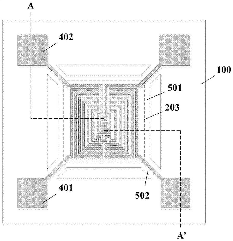
The invention provides an MEMS micro hot plate with a vacuum thermal insulation layer and a preparation method thereof. The MEMS micro hot plate comprises: a silicon substrate; a vacuum thermal insulation layer formed on the surface of the silicon substrate through an SON process; an insulating layer formed on the silicon substrate and the vacuum thermal insulation layer; a heating electrode and a testing electrode formed on the insulating layer and positioned right above the vacuum thermal insulation layer; a heating platform formed by sequentially etching the insulating layer and the silicon substrate along the periphery of the vacuum thermal insulation layer and provided with a suspended beam supporting structure; and a thermal insulation groove formed by etching or corroding the insulating layer and positioned in an area right below the heating platform. According to the invention, by means of the micro hot plate, the thermal insulation layer can be in the vacuum state through the SON technology to form the vacuum thermal insulation layer, and compared with air thermal insulation, the vacuum thermal insulation layer has more advantages in the aspect of restraining heat loss of the heating platform, so that heat conduction to the outside when the micro hot plate works can be effectively reduced so as to reduce heat loss and improve the temperature uniformity of the micro hot plate.

Description

Technical field [0001] The present disclosure relates to the field of microelectronics manufacturing techniques and microelectronic mechanical systems (MEMS) sensors, and in particular, to a MEMS microstructure having a vacuum insulation layer and a preparation method thereof. Background technique [0002] At present, gas sensors can be used to effectively prevent the occurrence of safety accidents, so the research and development of gas sensors is essential to prevent safety accidents. [0003] The metal oxide gas sensor is widely used in many fields such as petrochemical, metallurgical industries, environmental monitoring due to high sensitivity, rapid response, low cost, etc., but it still has problems such as large volume, high power consumption and poor selectivity. The development of MEMS technology has successfully pushed the gas sensor to achieve miniaturization, while low power, high selective multi-gas sensor has become a high-end MEMS gas sensor research hotspot. [00...

Claims


Application Information

Patent Timeline
Patent Type & Authority Applications(China)
IPC IPC(8): B81B7/02B81B7/00B81C1/00
CPCB81B7/02B81B7/0035B81C1/00277B81C1/00309B81C1/00333B81B2201/0292
Inventor 朱敏杰刘帅杜晓辉王洲刘丹
Owner INSTR TECH & ECONOMY INST P R CHINA
Learn More