
Stacking device for numerical control plate shearing

A stacking device and shearing technology, which is applied in the field of stacking devices for CNC shears, can solve the problems of difficult stacking and tidy, difficult long-term sustainable handling, easy to be pressed between plates, etc. The effect of labor force, efficiency improvement, and position accuracy assurance

Active Publication Date: 2022-01-28
江西辉泰电子有限公司
View PDF6 Cites 0 Cited by
  • Summary
  • Abstract
  • Description
  • Claims
  • Application Information

AI Technical Summary

Problems solved by technology

[0003] 1. A single plate has a certain weight, and long-term repeated handling will greatly consume the physical strength of the employees, making it difficult to carry it continuously for a long time, and it is difficult to stack neatly at the position observed by the naked eye;
[0004] 2. Due to the large area of ​​a single plate, multiple people need to work together to lift it. When the plate needs to be unloaded after being transported to the designated position, it is necessary to pull out the material at the same time. When one of them pulls out too fast, pull out the slower employee. Hands are easy to be pressed between the plates, and the plates at this time may also be misaligned after unloading

Method used


Image

  • Stacking device for numerical control plate shearing
  • Stacking device for numerical control plate shearing
  • Stacking device for numerical control plate shearing

Examples


Embodiment Construction

[0033]Embodiments of the present invention will be described below with reference to the drawings. In the process, in order to ensure the clarity and convenience of illustration, we may exaggerate the width of the lines or the size of the constituent elements in the diagram.

[0034] In addition, the following terms are defined based on the functions in the present invention, and may be different according to the user's or operator's intention or practice. Therefore, these terms are defined based on the entire content of this specification.

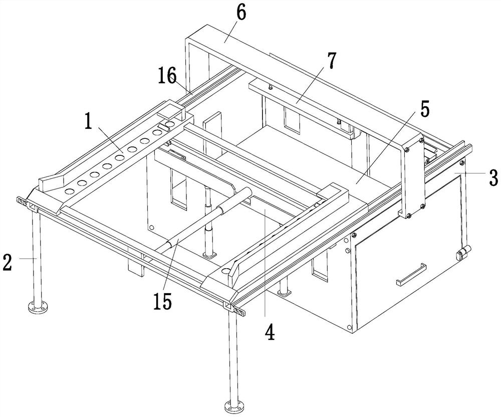
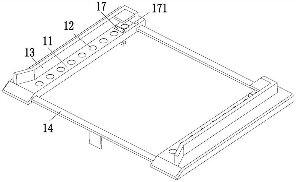
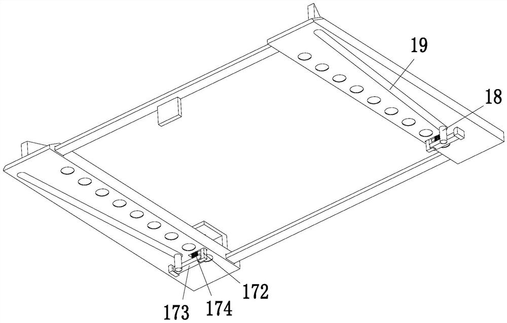
[0035] like Figure 1 to Figure 9 As shown, a palletizing device for CNC shearing boards includes a conveying mechanism 1, a support frame 2, a placing frame 3, a palletizing mechanism 4, a conveying platform 5, a U-shaped frame 6 and an air suction mechanism 7, and the upper end of the placing frame 3 A conveying mechanism 1 is installed on the side, and a support frame 2 is installed on the lower side of the front end of the conveying...


PUM


Abstract

The invention relates to a stacking device numerical control plate shearing. The device comprises a conveying mechanism, a supporting frame, a containing frame, stacking mechanisms, a conveying platform, a U-shaped frame and an air suction mechanism, the conveying mechanism is installed on the front side of the upper end of the containing frame, the supporting frame is installed on the lower side of the front end of the conveying mechanism, the stacking mechanisms are symmetrically installed at the front end and the rear end of the containing frame, a conveying platform is placed in the containing frame, a U-shaped frame is installed in the middle of the upper end of the containing frame, and an air suction mechanism is installed on the U-shaped frame. The problems that a single plate has a certain weight, is repeatedly carried for a long time, greatly consumes physical strength of staff, is difficult to carry for a long time continuously, and is difficult to stack tidily when being observed by naked eyes, and the problems that due to the fact that the area of a single plate is large, the single plate needs to be lifted by multiple persons together, the plate needs to be unloaded after being carried to a designated position, and when one person pulls out the material too quickly, the hand of the worker which pulls out the material slowly is prone to being pressed between the plates, and the like can be solved.

Description

technical field [0001] The invention relates to the technical field related to plate processing, in particular to a palletizing device for numerically controlled shearing plates. Background technique [0002] The CNC shearing machine is a kind of forging machine, which is a machine that uses one blade to make a reciprocating linear motion relative to the other blade to shear the plate. It uses the moving upper blade and the fixed lower blade to apply shearing force to metal sheets of various thicknesses with a reasonable blade gap, so that the sheets are broken and separated according to the required size, and the cut sheets need to be pushed out for processing. Palletizing, today's personnel usually determine the position by visual observation after manually lifting the board, so that the stacking is neat, but this method often encounters some problems in the actual operation process: [0003] 1. A single plate has a certain weight, and long-term repeated handling will gre...

Claims


Application Information

Patent Timeline
Patent Type & Authority Applications(China)
IPC IPC(8): B65G61/00B65G57/03
CPCB65G61/00B65G57/03
Inventor 李燕
Owner 江西辉泰电子有限公司
Learn More