
Automatic material clamping device

A clamping and automatic technology, applied in the direction of packaging, transportation and packaging, conveyors, etc., can solve the problems of affecting the aesthetics of finished products, increasing labor costs, leaving traces on plates, etc., to ensure the flexibility of multi-angle adjustment and work efficiency Synchronous lifting, accurate and controllable clamping position

Pending Publication Date: 2022-01-21
NINGBO TUOPU GROUP CO LTD
View PDF4 Cites 0 Cited by
  • Summary
  • Abstract
  • Description
  • Claims
  • Application Information

AI Technical Summary

Problems solved by technology

[0002] At present, in the field of auto parts processing, the raw materials of some parts are plate materials (hereinafter referred to as plates), and the plates need to go through multiple processes in the process of being processed into finished products. For example, the processed plates of some products need to be heated and baked before being molded. For the plates to be baked in the baking equipment, the traditional method is manual transfer; this method is not only low in work efficiency , the labor cost increases, and the contact area with the plate is large during the process of manually taking the plate, which is easy to leave marks on the plate, and the marks after baking will affect the aesthetics of the final product; in addition, because the plate is horizontal in the baking equipment Placed, after the baking is completed, it needs to be taken out and transferred to the next molding process. The mechanical fixture structure in the prior art cannot be well applied to this use environment where the plate is clamped on a plane.

Method used


Image

  • Automatic material clamping device
  • Automatic material clamping device
  • Automatic material clamping device

Examples


Embodiment Construction

[0024] In order to make the above objects, features and advantages of the present invention more comprehensible, specific embodiments of the present invention will be described in detail below in conjunction with the accompanying drawings.

[0025] In the description of the present invention, it should be noted that the orientations or positional relationships indicated by the terms "upper surface", "lower surface", "front and back", "left and right", "upper end", "lower end" are based on the drawings. The orientation or positional relationship shown is only for the convenience of describing the present invention and simplifying the description, but does not indicate or imply that the device or element referred to must have a specific orientation, be constructed and operated in a specific orientation, and therefore cannot be construed as limiting the scope of the present invention. limit.

[0026] In the description of the present invention, it should be noted that unless othe...


PUM


Abstract

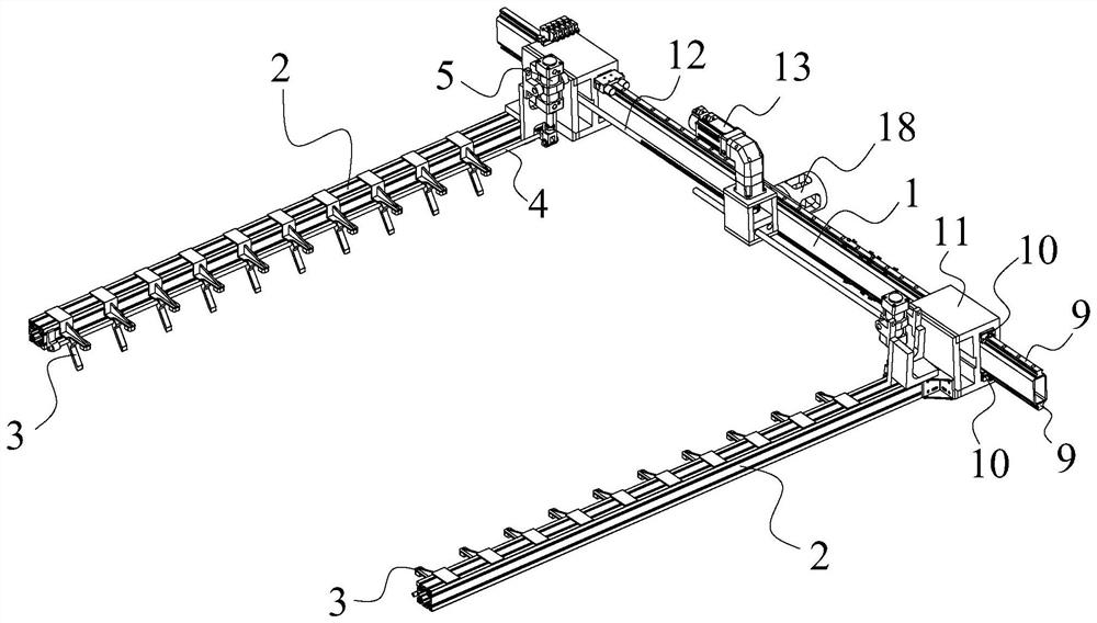
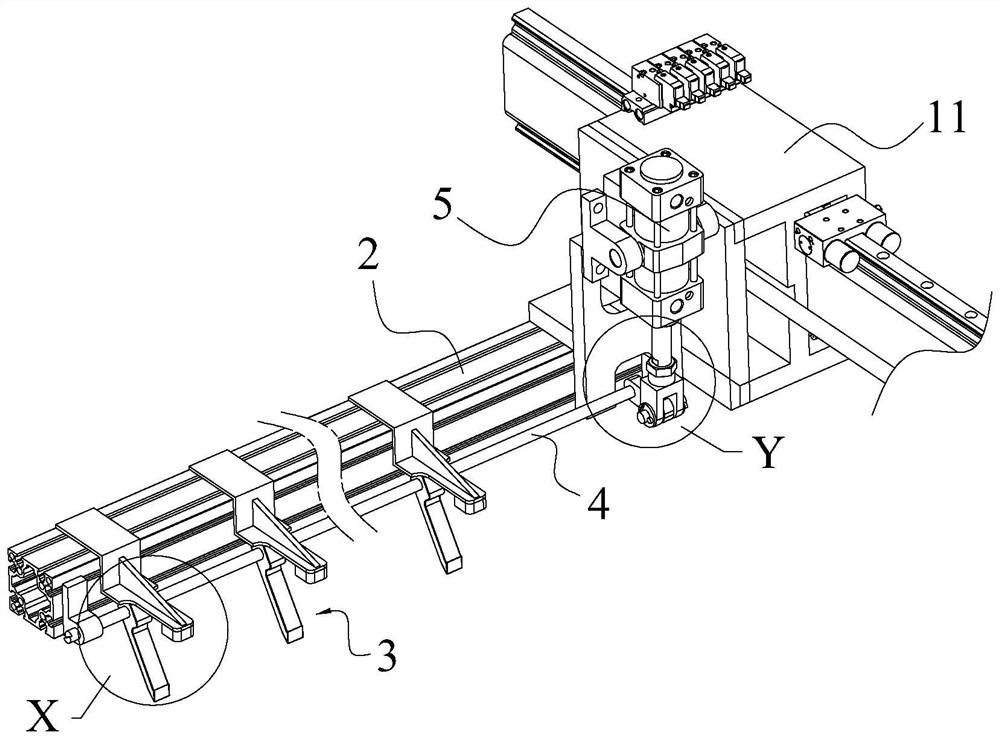
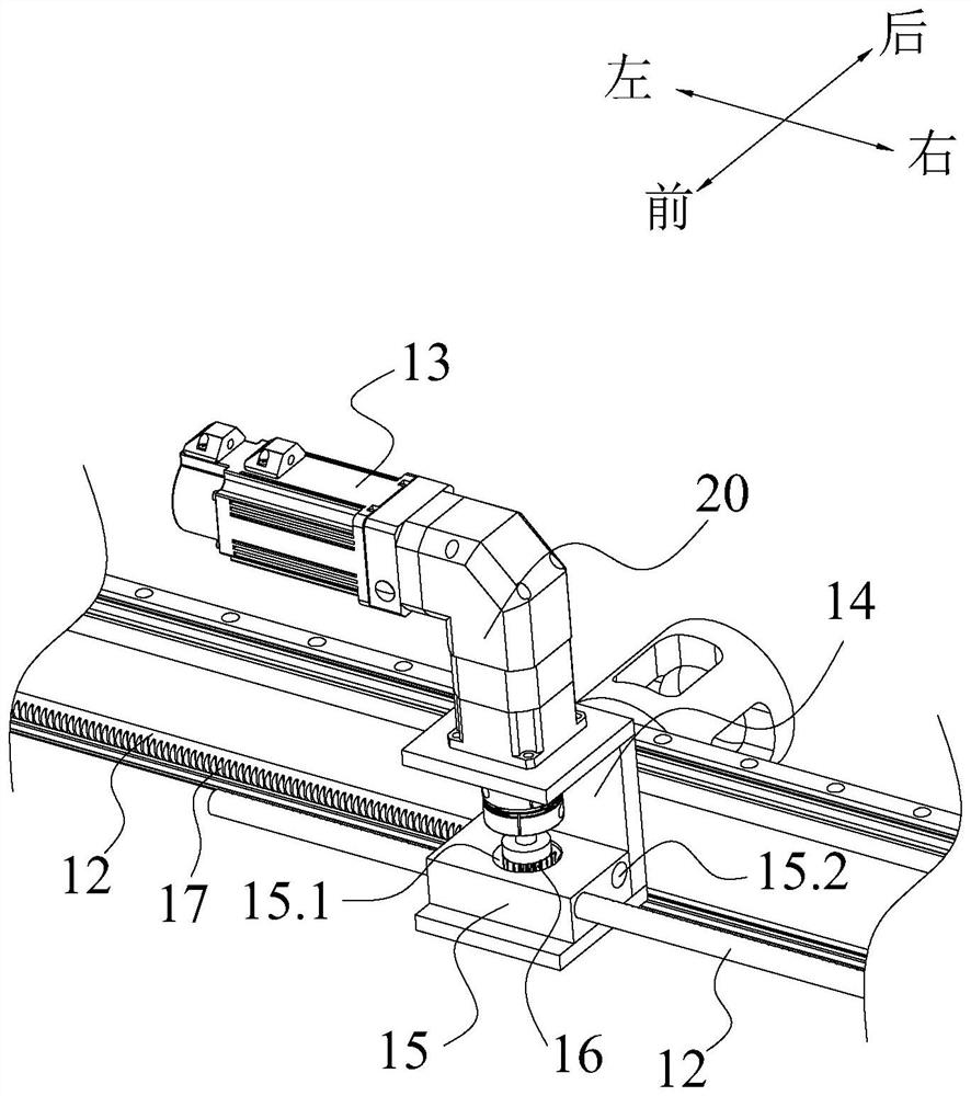
The invention provides an automatic material clamping device comprising an installation arm used for being detachably connected with a mechanical arm. Supporting arms capable of sliding in the length direction of the installation arm are arranged at the two ends of the installation arm correspondingly, and a first driving assembly used for driving the two supporting arms to be close to each other or separated from each other is arranged on the installation arm. Clamping mechanisms are arranged on the two supporting arms correspondingly. Wedge-shaped guide parts are arranged on the two clamping mechanisms correspondingly so that the two clamping mechanisms can clamp plate-shaped materials which are horizontally placed on a horizontal tabletop. According to the automatic material clamping device, automatic and stable clamping of horizontally-placed plates can be achieved, and the working efficiency is effectively improved.

Description

technical field [0001] The invention relates to the technical field of material clamping equipment, in particular to an automatic material clamping device. Background technique [0002] At present, in the field of auto parts processing, the raw materials of some parts are plate materials (hereinafter referred to as plates), and the plates need to go through multiple processes in the process of being processed into finished products. For example, the processed plates of some products need to be heated and baked before being molded. For the plates to be baked in the baking equipment, the traditional method is manual transfer; this method is not only low in work efficiency , the labor cost increases, and the contact area with the plate is large during the process of manually taking the plate, which is easy to leave marks on the plate, and the marks after baking will affect the aesthetics of the final product; in addition, because the plate is horizontal in the baking equipment ...

Claims


Application Information

Patent Timeline
IPC IPC(8): B65G47/90
CPCB65G47/901B65G2201/022B65G2207/42
Inventor 王金林杨杉苗朱波
Owner NINGBO TUOPU GROUP CO LTD
Learn More