
Automobile covering part storage equipment

A technology for automobile covers and equipment, which is applied to vehicle parts, wheels, internal accessories, etc., can solve the problems of humidity changes in indoor space, inconvenient moving and handling, and rusting of cover parts due to moisture, so as to facilitate fixed transportation and easy placement. , the effect of simple operation

Pending Publication Date: 2022-01-21
重庆千能实业有限公司
View PDF10 Cites 0 Cited by
  • Summary
  • Abstract
  • Description
  • Claims
  • Application Information

AI Technical Summary

Problems solved by technology

[0004] The purpose of the present invention is to solve the shortcomings of the existing storage equipment, which is easy to cause moisture and rust on the cover due to the change of humidity in the indoor space when the cover is placed, and is inconvenient to move and carry. A storage device for car covers

Method used


Image

  • Automobile covering part storage equipment
  • Automobile covering part storage equipment
  • Automobile covering part storage equipment

Examples


Embodiment 1

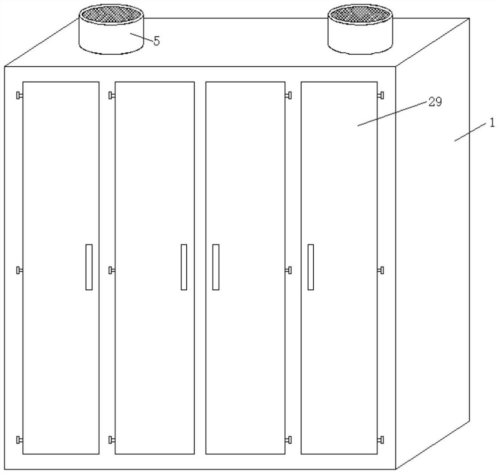
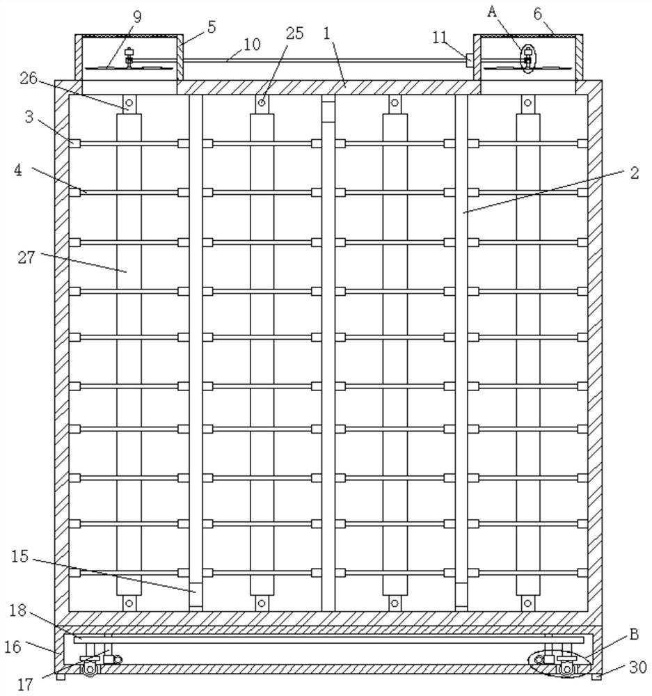
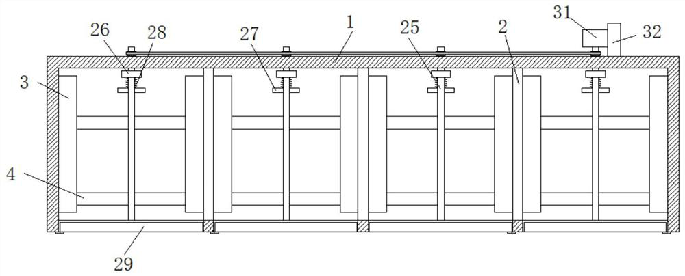
[0023] refer to Figure 1-5 , a kind of automobile cover storage equipment, comprises a cabinet body 1, three partitions 2 equally divided are fixedly installed on the inner wall of the cabinet body 1, and a plurality of Positioning plate 3, two connecting rods 4 are fixedly installed between the corresponding two positioning plates 3, and two symmetrical fixed boxes 5 are fixedly installed on the top of the cabinet body 1, and the fixed box 5 is provided with an air guide mechanism, which is fixed One side of the box 5 is fixedly equipped with a biaxial motor 11, and the output shaft of the biaxial motor 11 is fixedly equipped with a transmission rod 10. The transmission rod 10 is rotatably connected with the two fixed boxes 5, and the transmission rod 10 is connected with the air guiding mechanism. A through hole 15 is provided on the partition 2, a housing 16 is fixedly installed on the bottom of the cabinet body 1, and four symmetrically arranged backing plates 30 are fixe...

Embodiment 2

[0029] refer to Figure 1-5 , a kind of automobile cover storage equipment, comprises a cabinet body 1, three partitions 2 equally divided are fixedly installed on the inner wall of the cabinet body 1, and a plurality of Positioning plate 3, two connecting rods 4 are fixedly installed between the corresponding two positioning plates 3, and two symmetrical fixed boxes 5 are fixedly installed on the top of the cabinet body 1, and the fixed box 5 is provided with an air guide mechanism, which is fixed One side of the box 5 is fixedly equipped with a biaxial motor 11, and the output shaft of the biaxial motor 11 is fixedly equipped with a transmission rod 10. The transmission rod 10 is rotatably connected with the two fixed boxes 5, and the transmission rod 10 is connected with the air guiding mechanism. A through hole 15 is provided on the partition 2, a housing 16 is fixedly installed on the bottom of the cabinet body 1, and four symmetrically arranged backing plates 30 are fixedl...


PUM


Abstract

The invention belongs to the technical field of storage equipment, in particular to automobile covering part storage equipment, and provides the following scheme aiming at the problems that when the existing storage equipment is used for storing the covering parts, due to the humidity change of an indoor space, the covering parts are easily rusted due to humidity, and the covering parts are inconvenient to move and carry. The automobile covering part storage equipment comprises a cabinet body, three equally-divided partition plates are fixedly installed on the inner wall of the cabinet body, a plurality of positioning plates are fixedly installed on the sides, close to each other, of every two adjacent partition plates, two connecting rods are fixedly installed between every two corresponding positioning plates, two symmetrically-arranged fixing boxes are fixedly installed at the top of the cabinet body, air guide mechanisms are arranged in the fixing boxes, and double-shaft motors are fixedly installed on one sides of the fixing boxes. The automobile covering part storage equipment is easy to operate and convenient to use, the plurality of automobile covering parts can be conveniently placed, meanwhile, ventilation drying can be conducted, and fixing and transporting can be facilitated.

Description

technical field [0001] The invention relates to the technical field of storage equipment, in particular to a storage equipment for automobile cover parts. Background technique [0002] Automobile panels refer to the surface or internal parts of the space shape made of thin metal plates that cover the engine, chassis, cab, and body. According to function and location, it can be divided into three categories: external covering, internal covering and skeleton covering. They have different characteristics from general stamping parts in terms of process design, mold processing, equipment selection and quality control (dimensional tolerance, shape accuracy, part stiffness, surface quality), etc. Automobile cover parts need to be stored after processing. [0003] When the existing storage equipment places the cover parts, due to the change of humidity in the indoor space, it is easy to cause moisture and rust on the cover parts, and it is inconvenient to move and carry. Therefore,...

Claims


Application Information

Patent Timeline
Patent Type & Authority Applications(China)
IPC IPC(8): B65D25/02B65D25/10B65D25/24B65D81/05B65D81/26B65D85/68B60B33/06
CPCB65D25/101B65D25/02B65D25/24B65D81/05B65D81/263B65D85/68B60B33/06
Inventor 何亮
Owner 重庆千能实业有限公司
Learn More