Puncture positioning device for nerve intervention
A positioning device and nerve intervention technology, applied in the direction of puncture needles, trocars, etc., can solve the problems of adjusting the strength of clamping puncture needles, low flexibility, and the positioning device cannot meet the adjustment of needle entry angle, so as to reduce the possibility of slippage , the effect of improving safety
- Summary
- Abstract
- Description
- Claims
- Application Information
AI Technical Summary
Problems solved by technology
Method used
Image
Examples
Embodiment 1
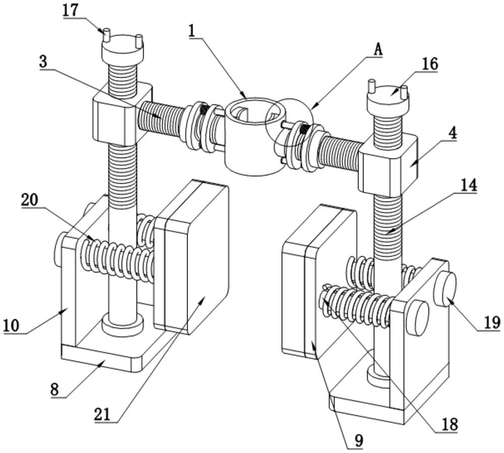
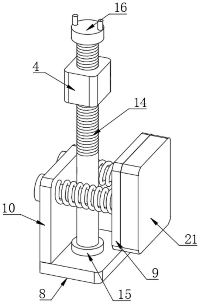
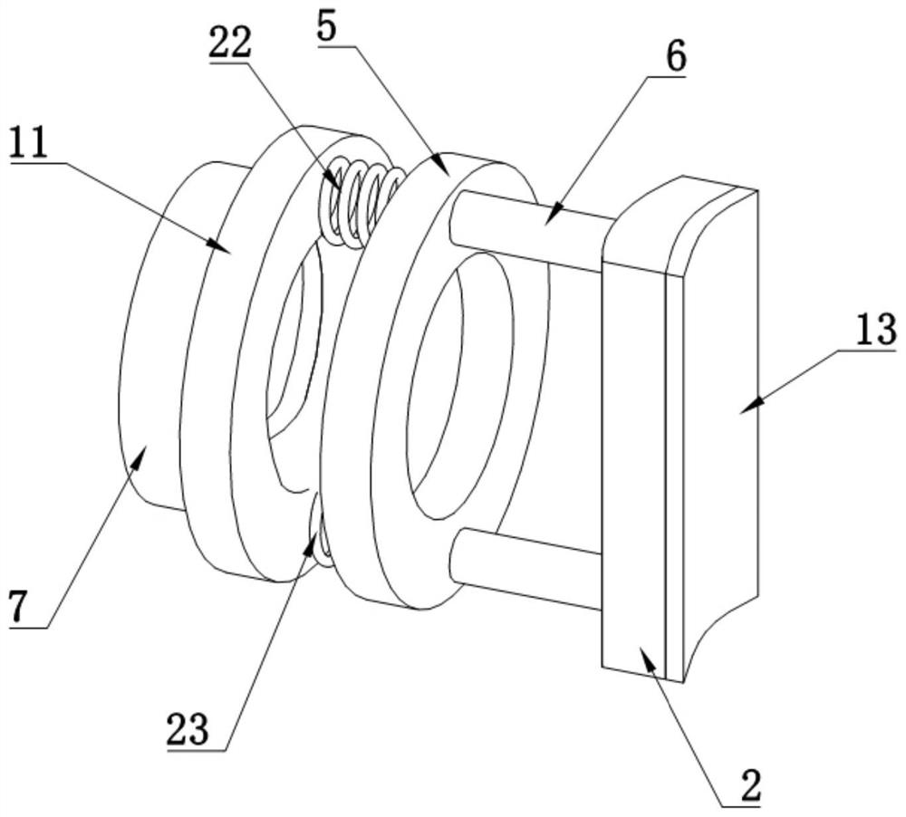
[0029] like Figure 1-5As shown, a puncture positioning device for nerve intervention includes a positioning tube 1, two positioning plates 2 are arranged in the positioning tube 1, and two first threaded columns 3 are fixedly connected to the positioning tube 1. The first threaded column 3. One end away from the positioning tube 1 is fixedly connected to the movable block 4, the first threaded column 3 is sleeved with a first movable ring 5, the positioning plate 2 is fixedly connected with two connecting columns 6, and one end of the connecting columns 6 penetrates the positioning tube The movable hole 12 on 1 is fixedly connected with the first movable ring 5; the diameter of the movable hole 12 is larger than the diameter of the connecting column 6, so that the first movable ring 5 can drive the connecting column 6 to move in the movable hole 2, thereby realizing the first The movable ring 5 drives the positioning plate 2 to move through the connecting column 6 .
[0030]...
Embodiment 2
[0036] When performing a puncture operation on a patient, due to the limitation of the patient's puncture site and body position, it is often necessary to adjust the angle at which the puncture needle penetrates the patient's body. Patients with different diseases require different needle insertion angles. To meet the requirements of the angle, the relevant components of the device have been further improved.
[0037] Specifically, as Figure 6-8 As shown, a pair of first electromagnets 24 are provided on the first movable ring 5 and the second movable ring 11 corresponding to both ends of the upper compression spring 22 , and the first movable ring 5 and the second movable ring 11 corresponding to both ends of the lower compression spring 23 are provided with a pair of first electromagnets 24 . A pair of second electromagnets 25 are arranged on the movable ring 11 .
[0038] After the puncture needle is clamped by the two clamping plates 2, when the needle insertion angle of...
Embodiment 3
[0040] In order to further control the two positioning plates 2 to adjust the needle insertion angle of the puncture needle and provide guidance for the operator, a second pressure sensor is provided at one end of the upper compression spring 22 and the lower compression spring 23 near the first movable ring 5; through the controller After controlling the first electromagnet 24 and the second electromagnet 25 on both sides of the positioning tube 1 to tilt the two positioning plates 2 and drive the puncture needle to adjust the angle, when the upper compression spring 22 or the lower compression spring 23 is compressed, the corresponding The pressure value measured by the corresponding second pressure sensor is F, and the compression amount of the upper compression spring 22 or the lower compression spring 23 is M=F / k, where k is the elastic coefficient of the upper compression spring 22 and the lower compression spring 23; After the compression spring 22 or the lower compressi...
PUM
 Abstract
Description
Claims
Application Information
 - R&D Engineer
- R&D Manager
- IP Professional
- Industry Leading Data Capabilities
- Powerful AI technology
- Patent DNA Extraction
Browse by: Latest US Patents, China's latest patents, Technical Efficacy Thesaurus, Application Domain, Technology Topic, Popular Technical Reports.
© 2024 PatSnap. All rights reserved.Legal|Privacy policy|Modern Slavery Act Transparency Statement|Sitemap|About US| Contact US: help@patsnap.com


