Exhaust device for cardiac surgery
A technology of surgical operation and exhaust device, which is applied in the direction of surgery, medical science, etc., can solve the problems of inconvenience, adjust the length of the fixing belt, etc., and achieve the possible effect of facilitating force and reducing sliding
- Summary
- Abstract
- Description
- Claims
- Application Information
AI Technical Summary
Problems solved by technology
Method used
Image
Examples
Embodiment 1
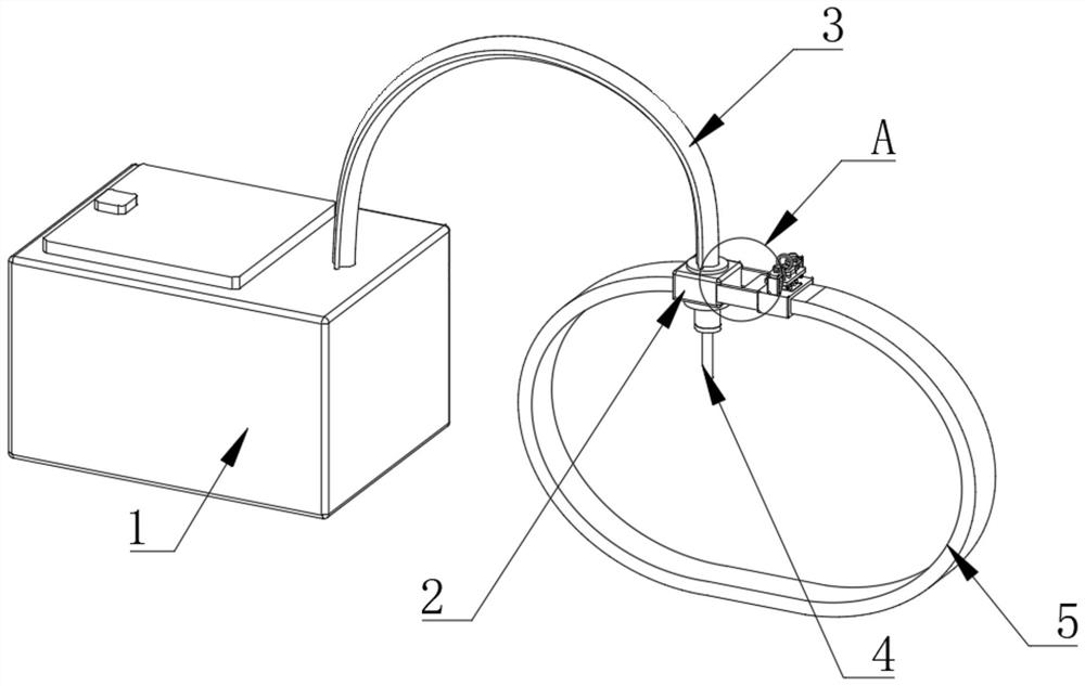
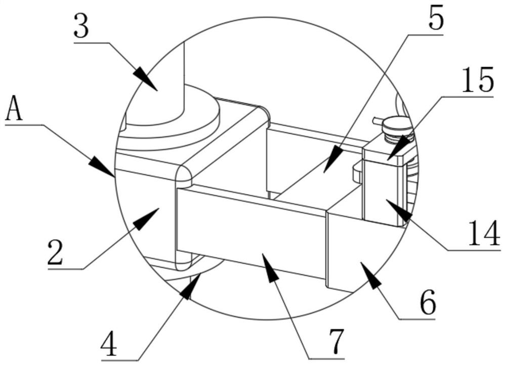
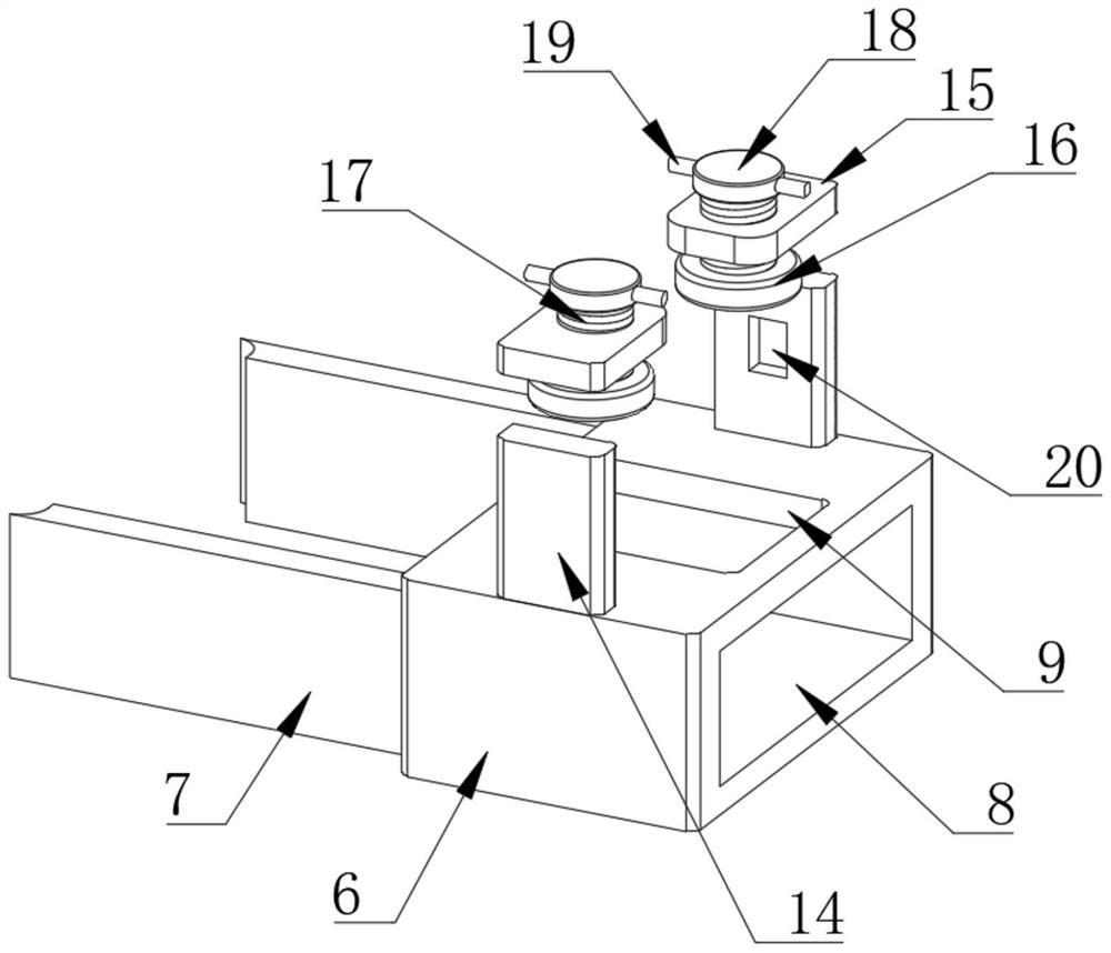
[0025] Embodiment one, by Figure 1 to Figure 4 Given, the present invention includes a main body 1, a pipeline base 2, an air extraction tube 3, a needle 4 and a fixing belt 5, the pipeline base 2 and the main body 1 are connected through an air extraction tube 3, the needle 4 is arranged at the bottom of the pipeline base 2, and the pipeline One side of the base 2 is provided with a fixed base 6, the fixed base 6 and the pipeline base 2 are connected by two connecting plates 7, one side of the fixed base 6 is provided with a first rectangular hole 8, and one end of the fixed band 5 is connected to the pipeline base. One side of the seat 2 is fixedly connected, the other end of the fixing band 5 runs through the first rectangular hole 8, the top inner wall of the first rectangular hole 8 is provided with a second rectangular hole 9, and a splint 10 is arranged in the second rectangular hole 9, and the splint 10 Adjusting plate 11 is arranged on the upper side, splint 10 and a...
Embodiment 2
[0026] Embodiment two, on the basis of embodiment one, by Figure 4 Given, the elastic unit includes several positioning posts 12 arranged on the top of the splint 10, the positioning posts 12 are fixedly connected with the splint 10, and the top ends of the positioning posts 12 run through the adjustment plate 11, and the outside of the positioning posts 12 is provided with a compression spring 24, which compresses The two ends of the spring 24 are respectively in contact with the splint 10 and the adjustment plate 11, the top of the adjustment plate 11 is provided with a movable seat 13, the top of the positioning column 12 is fixedly connected with the bottom of the movable seat 13, and the top of the movable seat 13 is provided with a pull ring 22. An anti-slip pad 23 is fixedly connected to the bottom of the splint 10, and the anti-slip pad 23 is in contact with the fixed belt 5, and the movable seat 13 is driven to move upward through the pull ring 22, so that the positio...
Embodiment 3
[0027] Embodiment three, on the basis of embodiment one, by image 3 Given, the pressing assembly includes a pressing plate 16 arranged below the top plate 15, the top of the pressing plate 16 is fixedly connected with a threaded post 17, the threaded post 17 runs through the top plate 15, the threaded post 17 and the top plate 15 are connected in a threaded connection, and the threaded post The top of 17 is fixedly connected with a fixed plate 18, and the fixed plate 18 is provided with a handle 19. By driving the fixed plate 18 to rotate, the threaded column 17 moves down relative to the top plate 15, and then adjusts the height of the pressing plate 16, which is adjusted by pressing the plate 16. The plate 11 moves down to adjust the distance between the adjusting plate 11 and the splint 10 , and then control the deformation degree of the compression spring 24 to adjust the strength of the splint 10 to press the fixing belt 5 .
PUM
 Abstract
Description
Claims
Application Information
 - R&D Engineer
- R&D Manager
- IP Professional
- Industry Leading Data Capabilities
- Powerful AI technology
- Patent DNA Extraction
Browse by: Latest US Patents, China's latest patents, Technical Efficacy Thesaurus, Application Domain, Technology Topic, Popular Technical Reports.
© 2024 PatSnap. All rights reserved.Legal|Privacy policy|Modern Slavery Act Transparency Statement|Sitemap|About US| Contact US: help@patsnap.com


