Aerial photography camera imaging time measuring device
A technology of time measurement and camera imaging, which is applied in the field of aerial photography, can solve problems that easily affect the accuracy of photo data and errors in imaging time measurement, and achieve the effect of improving the clarity, accuracy and field of view of shooting
- Summary
- Abstract
- Description
- Claims
- Application Information
AI Technical Summary
Problems solved by technology
Method used
Image

Examples
Embodiment 1
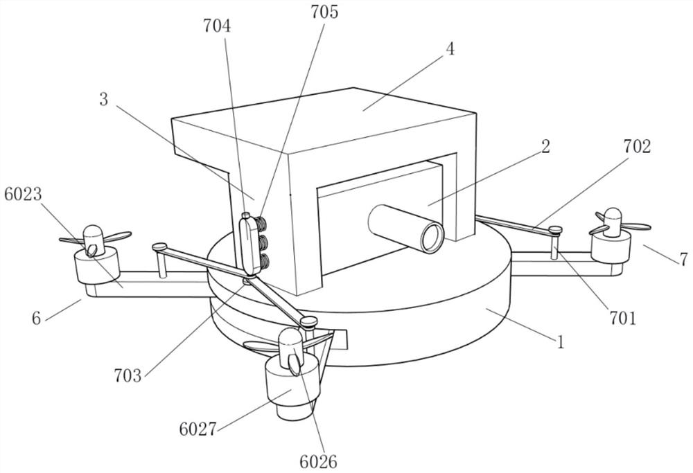
[0028] Embodiment one, by Figure 1-Figure 6 Given, the present invention comprises chassis 1, and photographic camera 2 is installed on the top of chassis 1, and fixed plate 3 is installed symmetrically on both sides of photographic camera 2, and fixed plate 3 is fixedly connected with chassis 1, and top plate 4 is installed on the top of fixed plate 3 The inside of the top plate 4 is equipped with an imaging time measurement mechanism 5, the bottom end of the top plate 4 is equipped with a field of view adjustment mechanism 6, the bottom end of the chassis 1 is also symmetrically equipped with supporting feet 8, and the front of the photographic camera 2 is equipped with a camera 201, and the photographic camera The top of 2 is equipped with shutter 202.
Embodiment 2
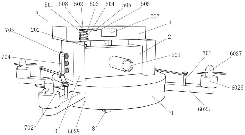
[0029] Embodiment 2, on the basis of Embodiment 1, the imaging time measuring mechanism 5 includes a movable groove 501 opened at the bottom of the top plate 4, a sleeve block 502 is installed inside the movable groove 501, and the bottom end of the sleeve block 502 is socketed with the shutter 202 A snap ring 504 is installed on the outside of the cover block 502, a spring 503 is installed on the top of the snap ring 504, a contact 508 is installed on the inner wall of the movable groove 501, a wire 506 is installed on one side of the contact 508, and a wire 506 is installed on one end of the wire 506. The power supply 507, the wire 506 is also electrically connected with the current sensor 505, and the top of the cover block 502 is equipped with a connecting contact;
[0030] First, after the motor 6026 is energized by the remote control, the motor 6026 drives the wings 6027 to rotate, causing the chassis 1 to fly. Shooting, when the shutter 202 moves downward, the cover blo...
Embodiment 3
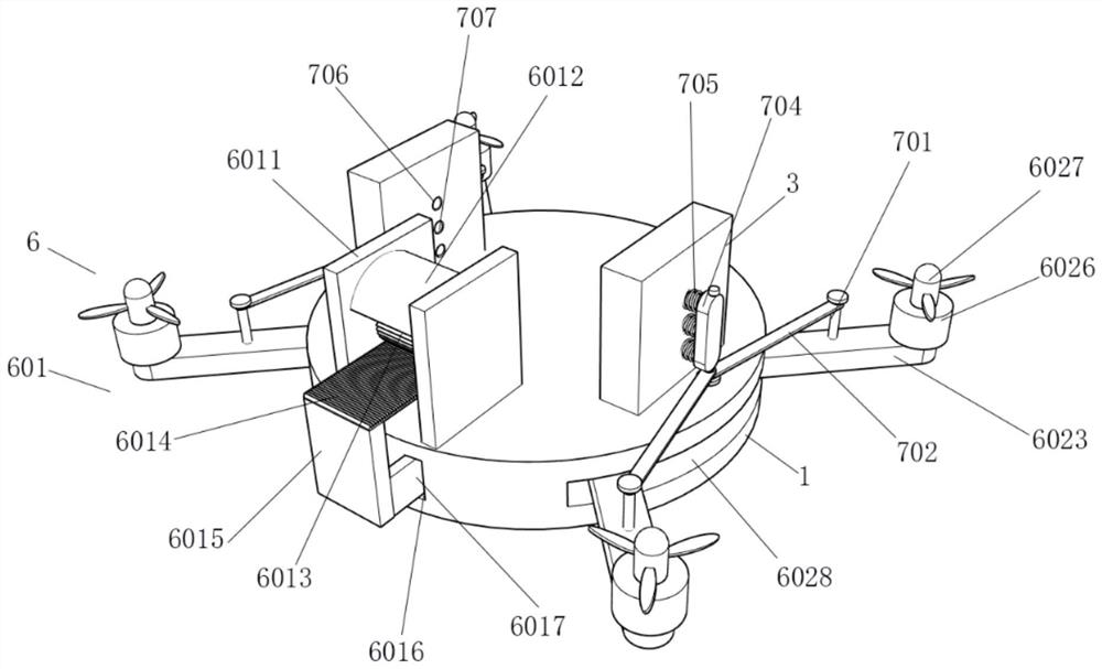
[0031]Embodiment 3, on the basis of Embodiment 2, the field of view adjustment mechanism 6 includes an active unit 601 and a driven unit 602, wherein the active unit 601 includes a side plate 6011 symmetrically installed at the bottom of the top plate 4, and the two side plates 6011 are symmetrical An electromagnet 6012 is installed, and a drive gear 6013 is rotationally connected between the two side plates 6011. The bottom end of the drive gear 6013 is meshed with a tooth plate 6014, and the bottom end of the tooth plate 6014 is equipped with a connecting plate 6015. One of the connecting plates 6015 A rack 6017 is installed symmetrically on the side, and the rack 6017 is plugged into the inside of the rack slot 6016, and the rack slot 6016 is symmetrically opened inside the chassis 1, the driving gear 6013 is installed between the upper and lower electromagnets 6012, and the power supply 507 and The two electromagnets 6012 are all electrically connected, and the current dire...
PUM
 Abstract
Description
Claims
Application Information
 - R&D
- Intellectual Property
- Life Sciences
- Materials
- Tech Scout
- Unparalleled Data Quality
- Higher Quality Content
- 60% Fewer Hallucinations
Browse by: Latest US Patents, China's latest patents, Technical Efficacy Thesaurus, Application Domain, Technology Topic, Popular Technical Reports.
© 2025 PatSnap. All rights reserved.Legal|Privacy policy|Modern Slavery Act Transparency Statement|Sitemap|About US| Contact US: help@patsnap.com