
Self-lock high-efficient rotary to linear mechanism

A technology of nut rotation, linear actuator, applied in the direction of gear transmission mechanism, brake actuator, mechanical equipment, etc.

Pending Publication Date: 2022-01-14
AKEBONO BRAKE IND CO LTD
View PDF5 Cites 0 Cited by
  • Summary
  • Abstract
  • Description
  • Claims
  • Application Information

AI Technical Summary

Problems solved by technology

Unfortunately, by increasing efficiency and removing self-locking threads, backdriving may still prevent the pads from applying full clamping force

Method used


Image

  • Self-lock high-efficient rotary to linear mechanism
  • Self-lock high-efficient rotary to linear mechanism
  • Self-lock high-efficient rotary to linear mechanism

Examples


Embodiment Construction

[0062] The explanations and illustrations presented herein are intended to acquaint others skilled in the art with its teachings, its principles and its practical application. Those skilled in the art can adapt and apply these teachings in various forms as best suited to the requirements of a particular application. Accordingly, the specific embodiments of the present teachings set forth are not intended to be exhaustive or limiting of the present teachings. The scope of the present teachings, therefore, should be determined not with reference to the description herein, but should be determined with reference to the appended claims, along with the full scope of equivalents to which such claims are entitled. The disclosures of all articles and references, including patent applications and publications, are hereby incorporated by reference for all purposes. Other combinations are also possible, as will be derived from the appended claims, which are also incorporated herein by r...


PUM


Abstract

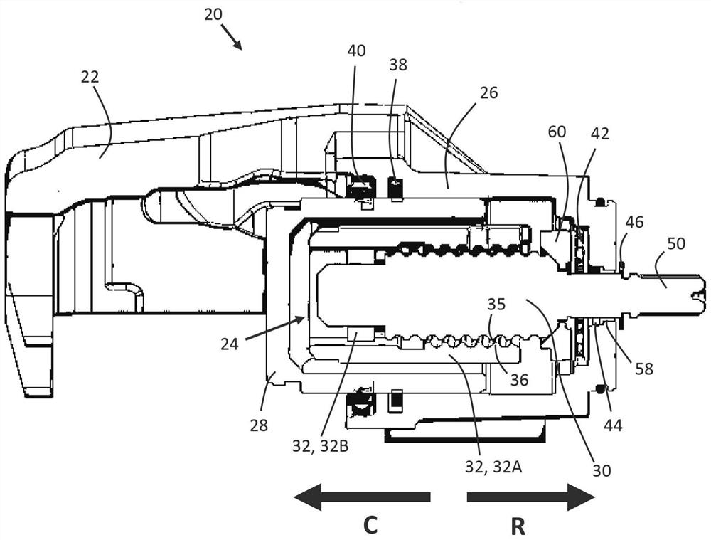
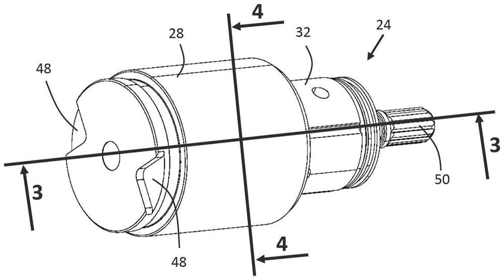
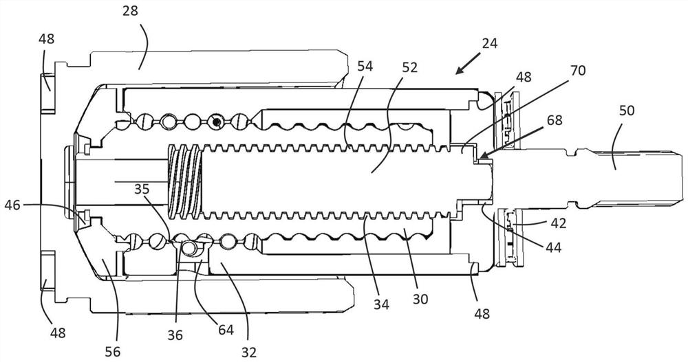
The invention relates to a self-lock high efficient rotary to linear mechanism. A rotary to linear actuator comprising: (a) a nut having a threading; (b) a spindle having an external threading and positioned at least partially within the nut; and (c) a drive shaft in communication with the nut to rotate the nut; wherein rotation of the drive shaft rotates the nut, and the threading of the nut engages the external threading of the spindle to move the spindle axially away from the drive shaft to drive a piston.

Description

technical field [0001] The present disclosure relates generally to a braking system and, more particularly, to a rotary to linear mechanism that drives a brake piston. Background technique [0002] Various braking systems are used in various vehicle and / or transportation applications. These braking systems may include one or more pistons, floating caliper housings or opposing piston (or fixed) caliper housings or combinations thereof. Typically, these braking systems will also include rotary-to-linear (RTL) actuators. [0003] The RTL actuator may be driven by a motor connected directly or indirectly to the RTL actuator. During brake application, the RTL actuator may receive power and at least a portion of the actuator may rotate. This rotation can then be converted into linear motion through one or more stages in the actuator to drive the piston towards one or more brake pads or brake shoes, thereby A clamping force is created between the one or more brake pads and the ...

Claims


Application Information

Patent Timeline
IPC IPC(8): F16D65/18F16D121/14F16D125/40F16D127/06
CPCF16D65/18F16D2121/14F16D2125/40F16D2127/06F16D65/183F16D55/226F16D2125/36F16D65/16F16D2121/24
Inventor W·M·阿尔-马施A·芭玛塔
Owner AKEBONO BRAKE IND CO LTD
Learn More