Oral implantation positioning device for edentulous jaw
A positioning device and edentulous jaw technology, which can be used in dentistry, dental implants, dental restorations, etc., and can solve problems such as reducing the accuracy of implants
- Summary
- Abstract
- Description
- Claims
- Application Information
AI Technical Summary
Problems solved by technology
Method used
Image
Examples
Embodiment 1
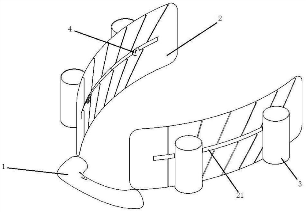
[0027] Such as figure 1 as shown, figure 1 It is a structural schematic diagram of the edentulous oral implant positioning device; the edentulous oral implant positioning device of the present invention includes a front-end fixing part 1, a rear-end extension part 2 and a sleeve 3, and the front-end fixing part 1 passes through the first The connection assembly is connected to the sleeve 3, the rear end extension 2 is connected to the sleeve 3 through the second connection assembly 4, the rear end extension 2 is provided with a rail groove 21, and the sleeve 3 The sleeve 3 can be moved along the guide rail groove 21 through the second connecting assembly 4 being movably arranged in the guide rail groove 21 .
[0028] The front end fixing part 1 is set as a metal plate in the form of a dental arch, and is fixed on the edentulous jaw with titanium nails, and the rear end extension part 2 is a metal plate extending in a direction away from the front end fixing part 1 , and the ...
Embodiment 2
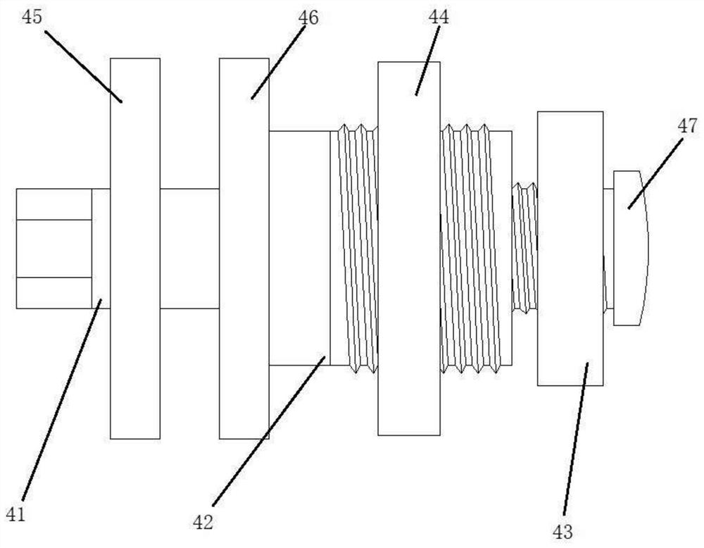
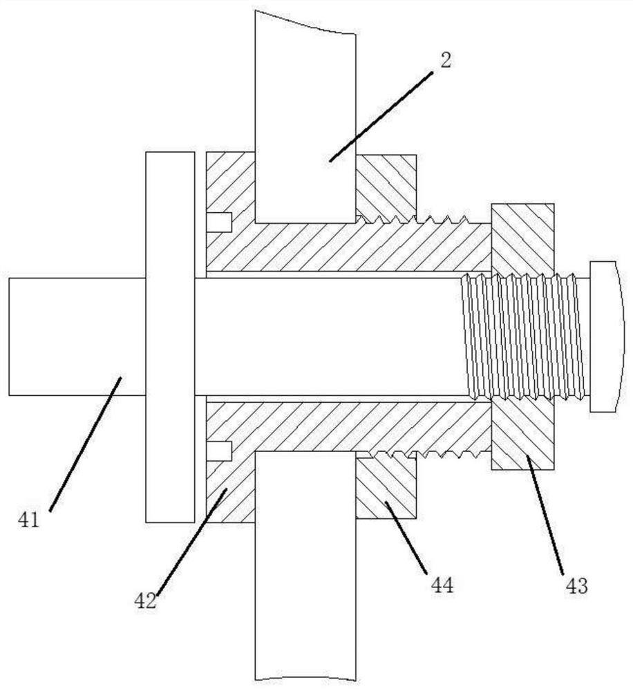
[0035] Such as figure 2 , image 3 as shown, figure 2 is a schematic structural diagram of the second connecting component; image 3 is a structural sectional view of the second connection assembly.
[0036] The second connection assembly 4 includes a rotating rod 41, a sliding block 42, a first locking nut 43 and a second locking nut 44, the sliding block 42 is provided with a rotating hole, and the rotating rod 41 is arranged in the rotating hole Inside, the rotating rod 41 can rotate freely in the rotating hole, one end of the rotating rod 41 is detachably connected with the sleeve 3, and the other end is threadedly connected with the first locking nut 43, the rotating rod 41 is provided with a first rotating disk 45, the sliding block 42 is arranged between the first rotating disk 45 and the first locking nut 43, and the sliding block 42 is arranged in the guide rail groove 21, so The sliding block 42 can move freely in the guide rail groove 21, the second rotating d...
Embodiment 3
[0045] The positioning part includes a positioning groove 48 provided on the first rotating disk 45 , a positioning hole 49 provided on the second rotating disk 46 , and a rolling roller provided in the positioning groove 48 and the positioning hole 49 at the same time. The ball 50 , the rolling ball 50 can roll circularly along the positioning groove 48 , so as to realize the relative rotation between the first rotating disk 45 and the second rotating disk 46 .
[0046] Such as Figure 4 as shown, Figure 4 It is a structural schematic diagram of the positioning groove; the positioning groove 48 includes several annular positioning segments 481 equidistantly arranged and a guide segment 482 connecting each of the positioning segments 481, the positioning segment 481 is set as a hemispherical groove, the The guide segment 482 is arranged as an arc groove surface and extends along the circumference arc to connect each of the positioning segments 481. The groove depth of the po...
PUM
 Abstract
Description
Claims
Application Information
 - R&D
- Intellectual Property
- Life Sciences
- Materials
- Tech Scout
- Unparalleled Data Quality
- Higher Quality Content
- 60% Fewer Hallucinations
Browse by: Latest US Patents, China's latest patents, Technical Efficacy Thesaurus, Application Domain, Technology Topic, Popular Technical Reports.
© 2025 PatSnap. All rights reserved.Legal|Privacy policy|Modern Slavery Act Transparency Statement|Sitemap|About US| Contact US: help@patsnap.com


