Wire harness rubber ring

A wire harness apron and apron technology, which is applied to electrical components and other directions, can solve the problems of disconnection between the wiring harness and the apron, damage to the bell mouth of the apron, affecting the life of the apron, etc. Service life, the effect of avoiding relative displacement

Active Publication Date: 2015-05-27
MIND ELECTRONICS APPLIANCE CO LTD
View PDF5 Cites 0 Cited by
  • Summary
  • Abstract
  • Description
  • Claims
  • Application Information

AI Technical Summary

Problems solved by technology

[0003] 1. The center line of the apron wire tube coincides with the center of the apron wire hole. When the wire harness needs to change direction after passing through the apron, the apron wire tube or its connection with the wire hole will become stretched. It not only affects the life of the apron but also affects the appearance;
[0004] 2. When the apron is installed through the sheet metal hole, it is necessary to pull the wire harness so that the apron snaps into the sheet metal hole. This operation will easily cause the relative position of the apron and the wire harness to move, resulting in improper assembly size of the wire harness, and it is easy to cause the wire harness and glue The connection position of the ring is out of joint, resulting in a quality hazard of water leakage;
[0005] 3. The existing rubber ring cannot prevent external noise from entering the cab;
[0006] 4. When adding additional lines such as configuration, pull wire or antenna to the existing apron, the wiring harness needs to be disassembled and reassembled or the bell mouth of the apron needs to be damaged

Method used


Image

  • Wire harness rubber ring
  • Wire harness rubber ring
  • Wire harness rubber ring

Examples


Embodiment Construction

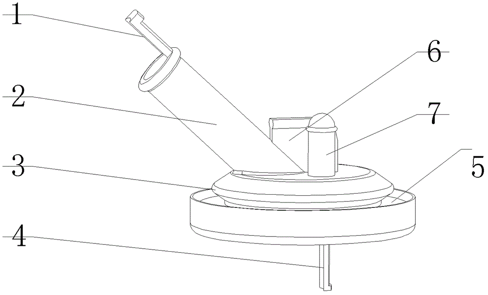
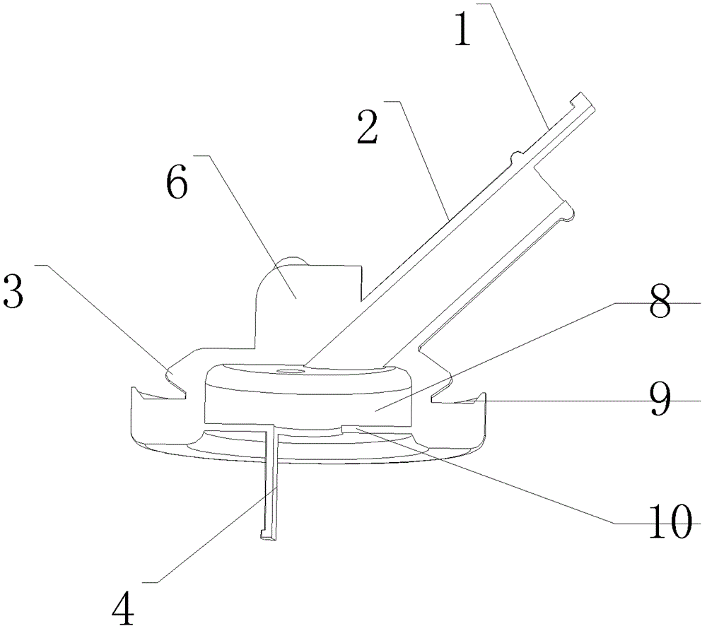
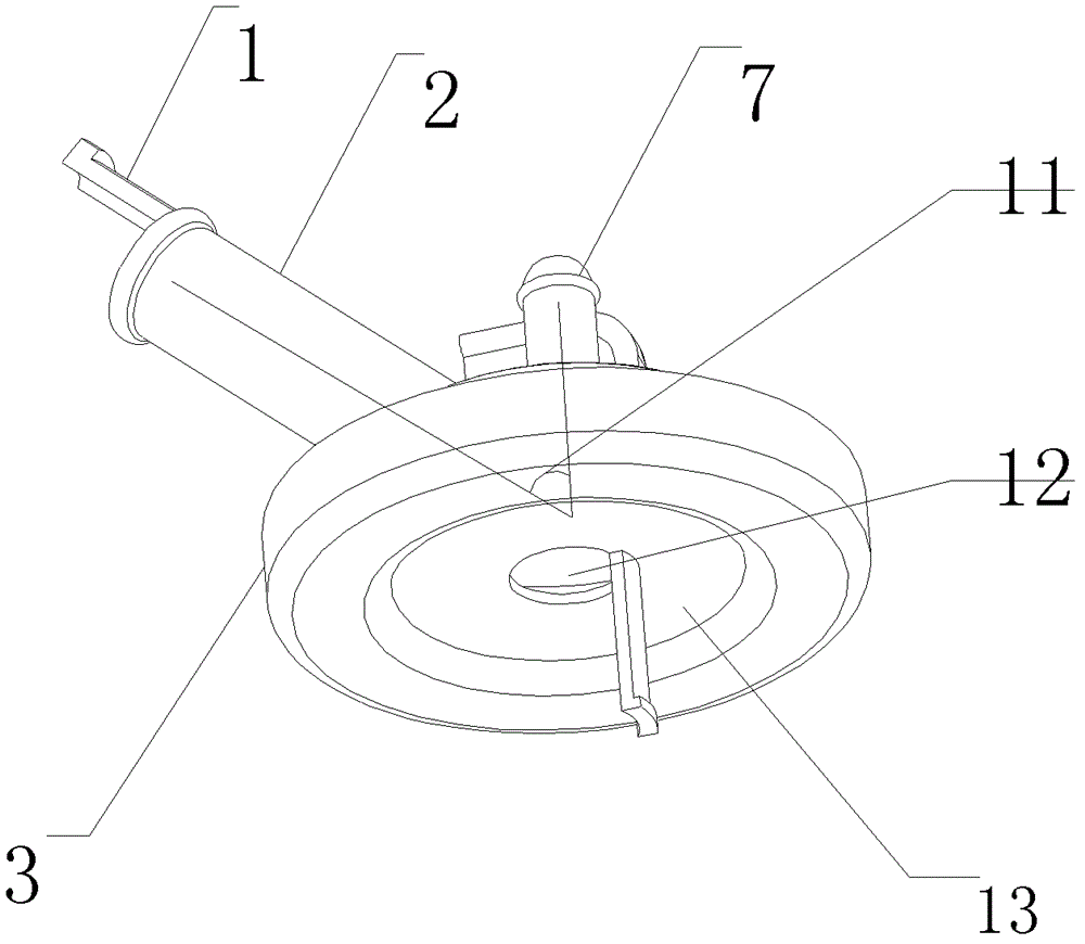
[0024] Such as Figure 1-3 As shown, a wire harness apron according to the embodiment of the present invention includes an apron main body 3, a cavity 8 is provided inside the apron main body 3, and a wire tube 2 and a pull tab are provided on the top of the apron main body 3. 6 and the spare blind hole 7, the bottom of the apron main body 3 is provided with a groove one 13, and the middle part of the groove one 13 is provided with a wire hole 12, and the wire pipe 2 and the wire hole 12 are all communicated with the cavity 8. The wiring harness fixing tongue 1 is connected to the wire passing pipe 2 . The bottom of the wire passing hole 12 is connected with a wire harness fixing tongue 2 4 . Bosses are provided at the ends of the first wire harness fixing tongue 1 and the second wire harness fixing tongue 4 . There is an included angle between the wire passing pipe 2 and the top surface of the rubber ring main body 3 . The spare blind hole 7 and the pull tab 6 are perpendi...


PUM


Abstract

The invention relates to a wire harness rubber ring, which comprises a rubber ring main body, wherein a cavity is formed in the rubber ring main body; a wire penetration pipe is arranged on the top of the rubber ring main body; a first groove is formed at the bottom of the rubber ring main body; a wire penetration hole is formed in the middle of the first groove; the wire penetration pipe and the wire penetration hole are respectively communicated with the cavity; and an included angle is formed between central lines of the wire penetration pipe and the wire penetration hole. The wire harness rubber ring has the advantages that by designing a certain angle between the central lines of the wire penetration pipe and the wire penetration hole, the movement direction of a wire harness is limited, the phenomenon that the assembled rubber ring is forced to stretch is avoided, and the service life of the rubber ring is prolonged; by adding a pull tongue and a wire harness fixed tongue, installation of the rubber ring and formation of a sheet metal hole are facilitated, relative displacement of the wire harness and the rubber ring is avoided, and disconnection of the wire harness and the rubber ring is avoided; and by forming the cavity which is soundproof, external noise is effectively prevented from entering a driving cab, and comfort is improved.

Description

technical field [0001] The invention relates to a wire harness rubber ring. Background technique [0002] With the continuous development of the automobile industry and the continuous innovation of automobile technology, people's requirements for automobiles are not limited to driving functions, and people pay more and more attention to comfort. At present, the wiring harness on the car is restricted by the rubber ring, which can only meet the basic requirements, and has the following disadvantages: [0003] 1. The center line of the apron wire tube coincides with the center of the apron wire hole. When the wire harness needs to change direction after passing through the apron, the apron wire tube or its connection with the wire hole will become stretched. It not only affects the life of the apron but also affects the appearance; [0004] 2. When the apron is installed through the sheet metal hole, it is necessary to pull the wire harness so that the apron snaps into the s...

Claims


Application Information

Patent Timeline
Patent Type & Authority Patents(China)
IPC IPC(8): H02G3/04
Inventor 杨刚许立杰康朝英
Owner MIND ELECTRONICS APPLIANCE CO LTD
Why Eureka
Try Eureka