Condensing device of cooking equipment and cooking equipment
A technology of condensing device and cooking equipment, which is applied in the direction of steam cooking utensils, cooking utensils, kitchen utensils, etc., which can solve the problems of poor condensation effect and large space occupation, and achieve the effect of less occupation, less layout space and beautiful appearance of the whole machine
- Summary
- Abstract
- Description
- Claims
- Application Information
AI Technical Summary
Problems solved by technology
Method used
Image
Examples
Embodiment 1
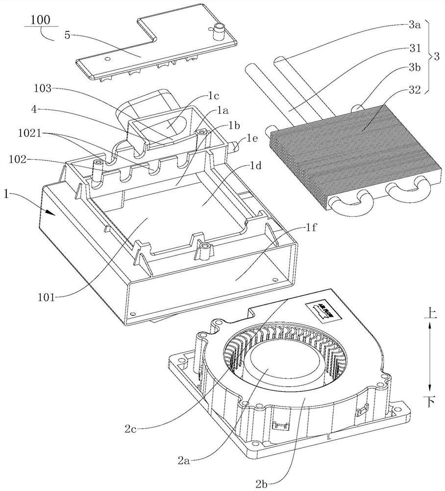
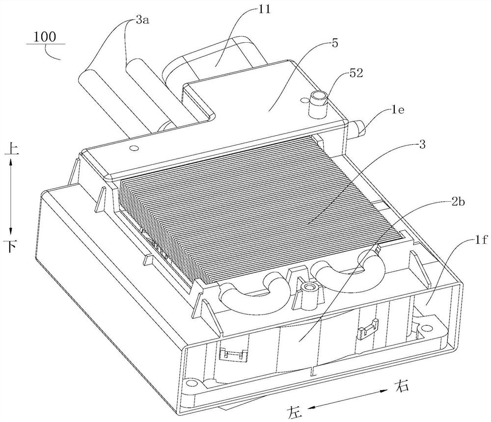
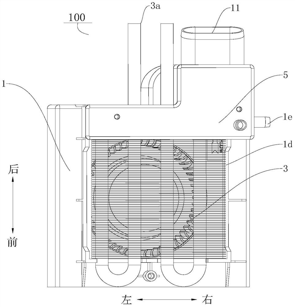
[0110] A condensing device 100, such as figure 1 As shown, it includes: a steam distribution shell 1, a fan 2a and a steam condensing assembly 3.
[0111] Among them, such as figure 1 with Image 6 As shown, the air-passing chamber 101, the gas-liquid separation chamber 102 and the air-mixing chamber 103 are respectively formed on the steam-distributing housing 1, and the air-mixing chamber 103 is respectively provided with a first communication port 1a, a second communication port 1b and a mixing and exhaust steam chamber. Port 1c, the air mixing chamber 103 is connected with the gas-liquid separation chamber 102 through the first communication port 1a, the air mixing chamber 103 and the air passage chamber 101 are connected through the second communication port 1b, and the air passage chamber 101 is provided with an air inlet 1d, such as Image 6 with Figure 7 As shown, one side of the gas-liquid separation chamber 102 is provided with a drain port 1e.
[0112] Such as ...
Embodiment 2
[0115] A condensing device 100 includes: a steam distribution shell 1 , a fan 2 a , a steam condensing assembly 3 , a water retaining dam 4 and an upper cover 5 .
[0116] The difference from Example 1 is that on the basis of Example 1, the water retaining dam 4 is vertically arranged in the steam distribution housing 1, and the upper part of the water retaining dam 4 forms the first communication port 1a, and the water retaining dam 4 separates the gas-liquid separation chamber. 102 and the air mixing chamber 103 are separated. Such as Figure 9 As shown, the upper cover 5 is detachably covered on the top of the gas-liquid separation chamber 102 and the air mixing chamber 103, as Figure 16 with Figure 18 As shown, the upper cover 5 is provided with a sealing edge 51 at the junction of the gas-liquid separation chamber 102 and the air mixing chamber 103 .
[0117] A cooking device 1000, such as Figure 10 with Figure 11 As shown, the difference from Embodiment 1 is tha...
Embodiment 3
[0119] A condensing device 100 includes: a steam distribution shell 1 , a fan 2 a , a steam condensing assembly 3 , a water retaining dam 4 and an upper cover 5 .
[0120] Different from Example 2, on the basis of Example 2, such as Figure 9 As shown, the bottom of the upper cover 5 is connected with a water retaining plate 53, and the water retaining plate 53 extends downwards and blocks at the retaining dam 4, as Figure 14 As shown, the water baffle 53 covers part of the first communication port 1a. Such as Figure 5 , Image 6 with Figure 8 As shown, the bottom wall of the gas-liquid separation chamber 102 is inclined downward along one end facing the drain port 1e. Such as figure 1 As shown, the discharge end 3b of the condensation pipe 31 is lower than the installation height of the drain port 1e.
[0121] Such as figure 2 with image 3 As shown, the steam condensing assembly 3 includes: a condensing pipe 31 and a plurality of fins 32 . The main part of the c...
PUM
 Abstract
Description
Claims
Application Information
 - R&D
- Intellectual Property
- Life Sciences
- Materials
- Tech Scout
- Unparalleled Data Quality
- Higher Quality Content
- 60% Fewer Hallucinations
Browse by: Latest US Patents, China's latest patents, Technical Efficacy Thesaurus, Application Domain, Technology Topic, Popular Technical Reports.
© 2025 PatSnap. All rights reserved.Legal|Privacy policy|Modern Slavery Act Transparency Statement|Sitemap|About US| Contact US: help@patsnap.com


