
Frequency conversion control system of boiler air pre-heater

A frequency conversion control, air preheater technology, applied in the control system, motor control, motor generator control, etc., can solve the problems of air preheater loss of power, reduce the reliability of the air preheater, poor reliability, etc., to improve safety and stability The ability to operate, reduce the risk of boiler shutdown, and ensure the reliable effect of power supply

Active Publication Date: 2022-01-11
HUANENG SHANTOU HAIMEN POWER GENERATION CO LTD
View PDF2 Cites 0 Cited by
  • Summary
  • Abstract
  • Description
  • Claims
  • Application Information

AI Technical Summary

Problems solved by technology

[0006] 1. The motor of the air preheater cannot be switched to the power frequency power supply smoothly after soft start, resulting in the loss of power of the air preheater
The reason is that the switching process of the contactor is complicated and the reliability is poor, especially the contactor coil and contacts of the equipment that has been in operation for many years have aging phenomena, which exacerbates the possibility of switching failure failures.
[0007] 2. The main motor of the air preheater cannot be used as a backup motor for the auxiliary motor
The reason is that the control loop only considers the locking loop that the main and auxiliary motors cannot start at the same time, and lacks the control loop for the auxiliary motor to jointly start the main motor.
[0008] The above two problems reduce the reliability of the air preheater operation, and even have the risk of boiler shutdown, which seriously affects the stable operation and economic benefits of the thermal power plant. Therefore, in order to ensure the stable operation of the air preheater, it is necessary to use the inverter to start the motor. Combined with the control method that the main motor and the auxiliary motor serve as backup for each other

Method used


Image

  • Frequency conversion control system of boiler air pre-heater

Examples


Embodiment 1

[0049] Main motor starts

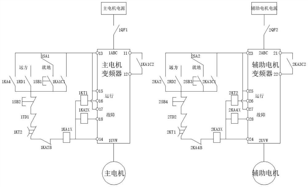
[0050] When the frequency converter of the auxiliary motor is in the stopped state and the first remote local transfer switch 1SA1 of the main motor is set at the local position, the first local start button 1SB1 is pressed, or the first remote local transfer switch 1SA1 of the main motor is set at the remote position When the first remote start button 1RD1 is pressed, the first electrified relay coil 1KA1X is energized to act, and the first normally open contact 1KA1C1 of the first electrified relay connected to the No. 13 contact 13 of the main motor inverter is closed to realize the first electrified The live function of the relay coil 1KA1X closes the second normally open contact 1KA1C2 of the first live relay connected to the No. 11 contact 11 of the main motor inverter, and realizes the conduction of the No. 11 contact 11 and No. 12 contact 12 of the main motor inverter. The frequency converter of the main motor starts, and the input terminal 1...

Embodiment 2

[0053] Auxiliary motor start

[0054]When the frequency converter of the main motor is in the stopped state and the second remote local transfer switch 2SA2 of the auxiliary motor is set at the local position, the second local start button 2SB3 is pressed, or the second remote local transfer switch 2SA2 of the auxiliary motor is set at the remote position Press the second remote start button 2RD2, the third electrified relay coil 2KA3X is energized, and the first normally open contact 2KA3C1 of the third electrified relay connected to the auxiliary motor frequency converter No. 23 contact 23 is closed to realize the third electrified relay coil 2KA3X The function of keeping live is to close the second normally open contact 2KA3C2 of the third live relay connected to the 21st contact 21 of the auxiliary motor inverter to realize the conduction of the 21st contact 21 and the 22nd contact 22 of the auxiliary motor inverter, and the auxiliary motor frequency conversion In this pro...

Embodiment 3

[0057] main motor stop

[0058] When the frequency converter of the main motor is in running state, the first remote local transfer switch 1SA1 of the main motor is set at the local position and the first local stop button 1SB2 is pressed, or the first remote local transfer switch 1SA1 of the main motor is set at the remote position Press the first remote stop button 1TD1, at this time the first charged relay coil 1KA1X will be de-energized and return, and the first normally open contact 1KA1C1 of the first charged relay connected to the No. 13 contact point 13 of the main motor inverter will be separated to release the first charged The function of keeping the electrification of the relay coil 1KA1X separates the second normally open contact 1KA1C2 of the first electrified relay connected to the No. 11 contact 11 of the main motor inverter, and releases the conduction between the No. 11 contact 11 and the No. 12 contact 12 of the main motor inverter. The frequency converter o...


PUM


Abstract

The invention relates to the technical field of air pre-heater control, in particular to a frequency conversion control system of a boiler air pre-heater. The system comprises a main motor power supply, an auxiliary motor power supply, a main motor control loop, an auxiliary motor control loop, a main motor frequency converter, an auxiliary motor frequency converter, a main motor and an auxiliary motor. Thefrequency converter is adopted to start directly, the soft starting requirements of the air pre-heater motor can be met, the output of a power frequency power supply can be directly provided for the motor on the basis of not changing a power supply loop, so that the loop switching of a double-contactor type is avoided; by changing a mode of directly dragging a frequency converter and optimizing a control loop, a power supply mode of a motor of the air pre-heater is simplified, a function of mutual standby of a main motor and an auxiliary motor is realized, the safe and stable operation capability of the air pre-heater of a thermal power plant is greatly improved, the risk of boiler shutdown is reduced, and the reliability of power supply is guaranteed; and meanwhile, the equipment maintenance difficulty of maintainers is reduced.

Description

technical field [0001] The invention relates to the technical field of air preheater control, and more specifically, relates to a frequency conversion control system for a boiler air preheater. Background technique [0002] The full name of air preheater is air preheater, which is an important boiler equipment in thermal power plants. [0003] The rotation of the air preheater is realized by the main motor or the auxiliary motor. At present, the starting method of the motor generally adopts the soft starter. After the start is completed, the soft starter is withdrawn through the switching circuit of the contactor, and the motor is directly powered by the power frequency power supply. . [0004] The general operation mode of the air preheater is driven by the main motor. When the auxiliary motor fails and the auxiliary motor fails, the air preheater loses power and stops. [0005] There are two main problems with this approach: [0006] 1. After the soft start of the air p...

Claims


Application Information

Patent Timeline
Patent Type & Authority Applications(China)
IPC IPC(8): H02P1/30H02P1/02H02P27/04H02P29/028F23L15/00
CPCH02P1/30H02P1/024H02P1/026H02P27/04H02P29/028F23L15/00Y02E20/34
Inventor 陈博徐兴国黄旭鹏陈明光张家宽吴斌黄俊炳
Owner HUANENG SHANTOU HAIMEN POWER GENERATION CO LTD
Learn More