
Composite continuous pipe gas production method

A technology for coiled tubing and gas production, applied in drilling pipes, casings, production fluids, etc., can solve problems such as affecting production efficiency, high cost, time-consuming and labor-intensive, etc., to improve production efficiency, prolong life cycle, and reduce production costs. Effect

Pending Publication Date: 2022-01-11
贵州页岩气勘探开发有限责任公司 +1
View PDF0 Cites 0 Cited by
  • Summary
  • Abstract
  • Description
  • Claims
  • Application Information

AI Technical Summary

Problems solved by technology

However, the process of replacing the velocity string is time-consuming and labor-intensive, affecting production efficiency and high cost

Method used


Image

  • Composite continuous pipe gas production method
  • Composite continuous pipe gas production method
  • Composite continuous pipe gas production method

Examples


Embodiment 1

[0072] This embodiment provides a composite continuous tube gas collection method, including:

[0073] S100, a composite continuous tube having a cross-sectional area adjustable working channel is loaded into a gas receiving well, and the gas passage of the gas well includes the working channel;

[0074] S200, when the liquid height of the gas reaches the preset threshold, the cross-sectional area of ​​the working passage is reduced to improve the flow rate of the inner gas in the well through the gas passage.

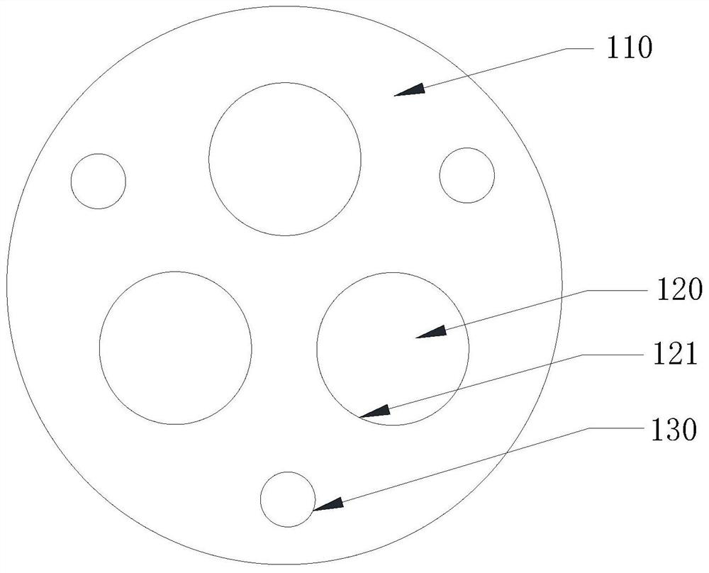
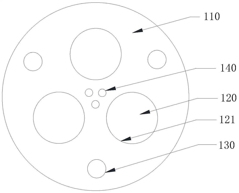
[0075] The working channel consists of three independent channels 120. At the initial stage of the work, the execution unit 500 controls three independent channel 120 simultaneously on, at this time, the gas in the gas is in the maximum gas-free cross-section state.

[0076] When the in-well fluid height reaches the preset threshold, the execution unit 500 controls one of the separate channels 120 to be turned off, at which time the gas well is passed through two separate ...

Embodiment 2

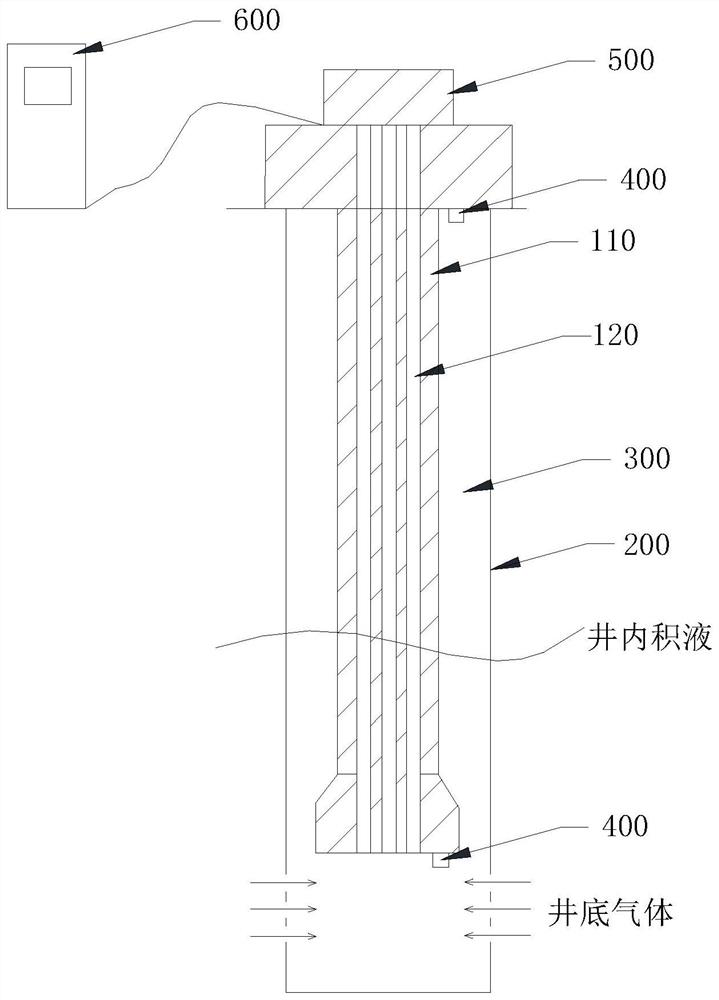
[0080] This embodiment provides a composite continuous pipe gas production method, comprising an adjustable cross-sectional area having a working channel of the tube into a continuous composite gas production well, the working channel 120 comprises three separate channels. Gas production well having within the sleeve 200, the sleeve extends into the composite coiled tubing 200, outer sleeve 200 and the inside of the composite coiled tubing annulus 300 is formed. Gas passage of gas production well comprises three separate annular channels 300 and 120. The environmental gas production well by monitoring the real-time monitoring unit 400.

[0081] In the initial stage of the work, an execution unit 500 controls three separate annular channels 300 and 120 are turned on simultaneously at this time is taken the maximum gas production wells sectional state.

[0082] When the height of the well fluid reaches a predetermined first threshold value, the controller 600 performs the control un...


PUM


Abstract

The invention discloses a composite continuous pipe gas production method which comprises the steps: mounting a composite continuous pipe with a working channel with the adjustable sectional area in a gas production well, wherein a gas production channel of the gas production well comprises the working channel; and when the height of an accumulated liquid in the gas production well reaches a preset threshold value, reducing the sectional area of the working channel, so as to increase the flow speed of the gas in the well flowing through the gas production channel. A natural gas well can be continuously produced by adjusting the section of the working channel, so that time and manual operation are effectively saved, the production efficiency is improved, and the production cost is reduced.

Description

Technical field [0001] The present application relates to the technical field of oil and gas mining, and in particular, to composite continuous tubes. Background technique [0002] The velocity column is a small diameter tube that is incorporated into the wellbore in the wellbore in the wellbore. The natural gas well of the fluid in the wellbore can enter the water drowning period to restore production. Selecting the speed tube diameter is a result of complex calculations of a related gas reservoir condition. The diameter is too large, the gas flow rate will decrease, resulting in elevated fluid in the well, and the choice is too small to affect gas efficiency. [0003] In order to achieve natural gas well, the speed tube is used for a period of time, which can replace the speed tube column in diameter, and further increase speed in the well gas in the well. However, the process of replacing the speed pillar is expensive, affecting production efficiency, and high cost. Inventive...

Claims


Application Information

Patent Timeline
IPC IPC(8): E21B43/00E21B17/18E21B43/12
CPCE21B43/121E21B17/18E21B43/12
Inventor 赵凯林忠灿于继良冯国竟张福齐园园李海龙吴盼赵志良张向锋
Owner 贵州页岩气勘探开发有限责任公司
Learn More