
Material guiding and dust falling spiral of direct thermal desorption rotary kiln equipment for soil remediation

A soil remediation and thermal desorption technology, which is applied in the field of soil remediation direct thermal desorption rotary kiln equipment, can solve the problems of increasing the pressure of the dust removal system, returning materials, and increasing the amount of flue gas, so as to improve the conveying capacity, The effect of reducing dust and reducing caking

Pending Publication Date: 2022-01-11
CSSC NANJING LUZHOU ENVIRONMENT PROTECTION CO LTD
View PDF0 Cites 0 Cited by
  • Summary
  • Abstract
  • Description
  • Claims
  • Application Information

AI Technical Summary

Problems solved by technology

However, due to its own physical and chemical properties when the soil is fed, it is prone to phenomena such as material return and agglomeration, which will cause the screw to be blocked and affect the operation of the entire system.
[0005] In addition, the tail gas directly thermally desorbed enters the tail gas treatment device through the feed screw, and the flue gas volume is large and the desorbed soil particles are entrained. Due to the small particle size of the soil, high temperature, and low moisture, the dust phenomenon is serious and increases. Due to the pressure of the follow-up dust removal system, some particles escape from the screw feed port, resulting in serious dust pollution on the project site

Method used


Image

  • Material guiding and dust falling spiral of direct thermal desorption rotary kiln equipment for soil remediation
  • Material guiding and dust falling spiral of direct thermal desorption rotary kiln equipment for soil remediation

Examples


Embodiment Construction

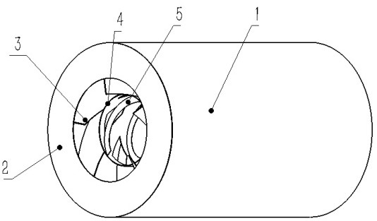
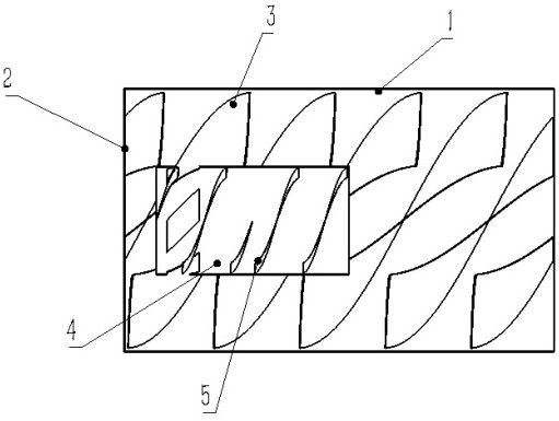
[0017] see figure 1 and figure 2 , this embodiment provides a direct thermal desorption rotary kiln equipment for soil remediation according to the present invention. The sealing port 2 at one end constitutes the outer chamber, the inner cylinder 4 is arranged in the outer chamber, the axis of the inner cylinder 4 and the axis of the shell 1 are on the same line, and several pieces of outer spiral blades 3 are evenly arranged in the outer chamber along the axis The cavity of the shell 1 is divided into several sub-outer cavities, and several pieces of outer spiral blades 3 are evenly sleeved on the outer side of the cylinder wall of the inner cylinder 4, and several pieces of internal spiral blades are evenly distributed along the axis of the inner cylinder 4. The vane 5 and the wall of the inner cylinder 4 are uniformly provided with quadrilateral holes equal to the number of outer spiral blades 3 socketed thereon.

[0018] The end of the shell 1 away from the sealing port...


PUM


Abstract

The invention relates to a material guiding and dust falling spiral of direct thermal desorption rotary kiln equipment for soil remediation. The material guiding and dust falling spiral comprises an outer shell, a sealing opening, outer spiral blades, an inner cylinder and inner spiral blades; the outer shell and the sealing opening formed in one end of the outer shell form an outer cavity; the inner cylinder is arranged in the outer cavity; the axis of the inner cylinder and the axis of the outer shell are located on the same straight line; the plurality of outer spiral blades are evenly arranged in the outer cavity along the axis to divide the cavity of the shell into a plurality of branch outer cavities; the outer spiral blades are evenly connected to the outer side of the cylinder wall of the inner cylinder in a sleeving mode; the plurality of inner spiral blades are evenly distributed in the inner cavity of the inner cylinder along the axis of the inner cavity; and quadrilateral holes with the number equal to that of the outer spiral blades sleeving the inner cylinder are uniformly formed in the cylinder wall of the inner cylinder. Soil entering the spiral is evenly scattered into the branch cavities through the quadrilateral holes in the inner cylinder and cannot be accumulated at the bottom of the spiral in quantity, the caking and material returning phenomena of the soil are reduced, and the conveying capacity of the spiral is improved.

Description

technical field [0001] The invention belongs to the technical field of environmental protection material guide equipment, and in particular relates to a material guide and dust reduction screw for direct thermal desorption rotary kiln equipment for soil restoration. Background technique [0002] With the adjustment of my country's industrial structure and the development of urbanization, a large number of organically polluted sites have been left after the relocation of a large number of pesticide and chemical companies, which has brought serious environmental risks and urgently needs to be repaired quickly and effectively. Direct thermal desorption technology has the advantages of wide treatment range, high heat transfer efficiency, and large treatment capacity, and is one of the main technologies for organic pollution site remediation. [0003] The direct thermal desorption technology sends the polluted soil to the thermal desorption device after being pretreated by crushi...

Claims


Application Information

Patent Timeline
Patent Type & Authority Applications(China)
IPC IPC(8): B09C1/06B01D45/08
CPCB09C1/06B01D45/08
Inventor 褚维平支晓欢张永良周永贤朱晶晶周浩陈纪赛
Owner CSSC NANJING LUZHOU ENVIRONMENT PROTECTION CO LTD
Learn More