
Device for reducing mechanical loads under and in a functional component such as a PTC element

A technology of positive temperature coefficient and functional components, applied in the direction of resistors with positive temperature coefficient, resistors with negative temperature coefficient, electrical components, etc., can solve the problems of unfavorable heat export, reduce stress level and improve contact Effect of pressure distribution, mechanical stress reduction

Pending Publication Date: 2022-01-07
ROBERT BOSCH GMBH
View PDF0 Cites 0 Cited by
  • Summary
  • Abstract
  • Description
  • Claims
  • Application Information

AI Technical Summary

Problems solved by technology

Furthermore, it has been found that the non-area-acting contact pressure distribution achieved by means of spring clips is also unfavorable for heat dissipation

Method used


Image

  • Device for reducing mechanical loads under and in a functional component such as a PTC element
  • Device for reducing mechanical loads under and in a functional component such as a PTC element
  • Device for reducing mechanical loads under and in a functional component such as a PTC element

Examples


Embodiment Construction

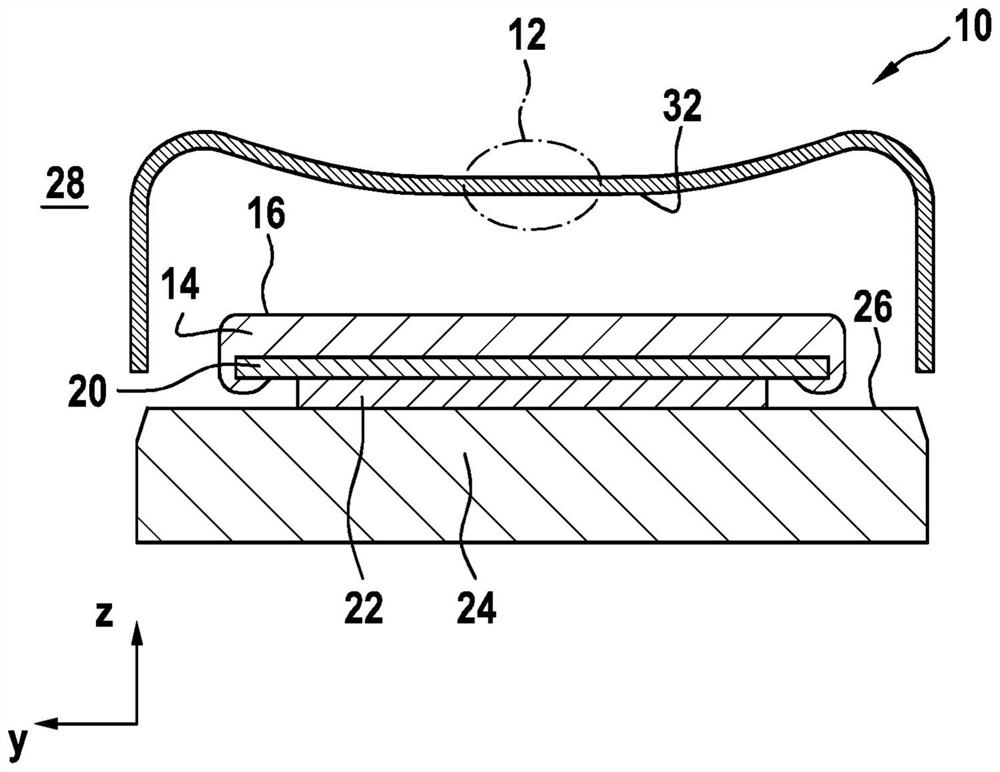
[0031] figure 1 The fastening device 10 proposed according to the invention is shown in its relaxed state 28 .

[0032] as by figure 1 It is known that the fastening device 10 proposed according to the invention is embodied, for example, as a spring clip and comprises a middle part 12 . The middle part 12 has a contact side 32 on the side facing the cover 14 . in accordance with figure 1 In the view of , the region of the contact side 32 of the middle part 12 is implemented straight. On both sides of the central part 12 , the first connecting plate 82 and the second connecting plate 84 of the fastening device 10 extend parallel to each other.

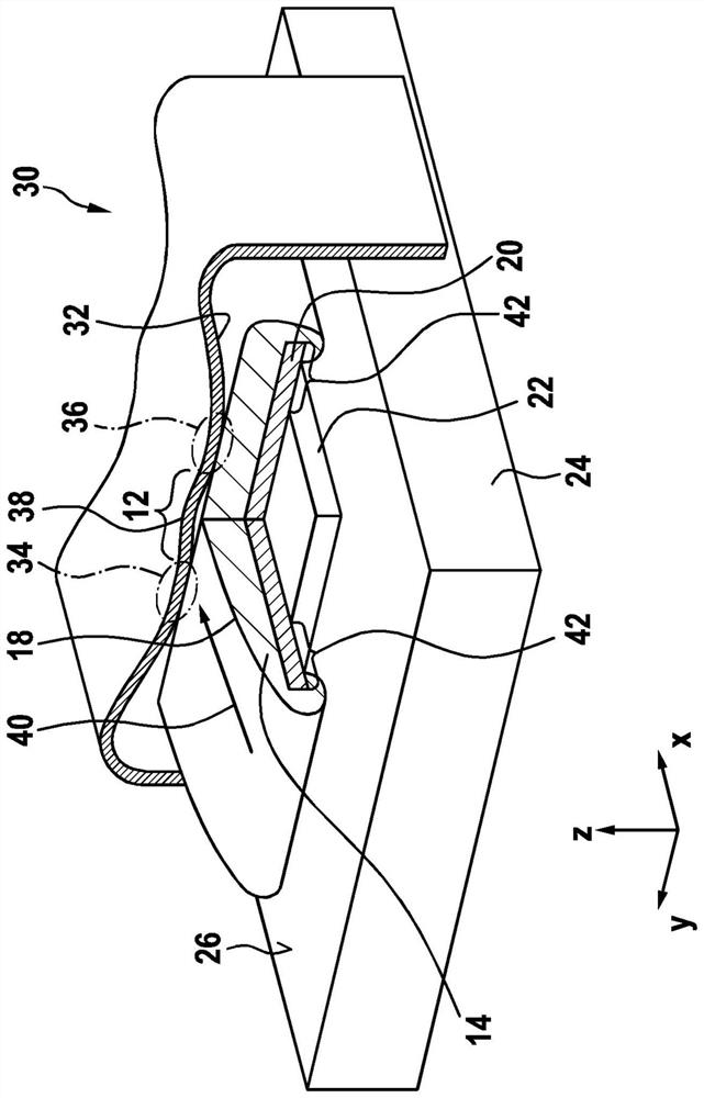
[0033] The fixing device 10 is arranged above the cover 14 . Cover 14 can have as figure 1 The flat upper side 16 shown in ; alternatively there is also the following possibility: According to image 3 A similar view of FIG. 10 implements the cover 14 with a curved upper side 18 . The cover 14 is manufactured from a plastic mate...


PUM


Abstract

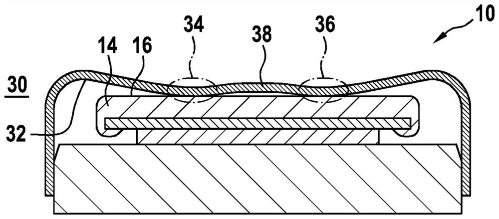
The invention relates to a device for reducing mechanical loads under and in a functional component (22), in particular a PTC element. Said functional component is arranged between a current-carrying element (20), which has a cover (14), and a thermal mass (24). A fastening device (10) has, within a center part (12), a flat or concavely curved contact side (32). Said contact side acts on a top side (18) of the cover (14) in the loaded state (30) of the fastening device (10). A first contact region (34) and a second contact region (36) are separated from each other by a raised portion (38) of the material of the center part (12) of the fastening device (10) that is designed in the form of a spring clip. The design of the first contact region (34) and the design of the second contact region (36) result in the distribution of a holding force and in a substantial reduction in the absolute height of the contact pressure maxima.

Description

technical field [0001] The invention relates to a device for reducing the mechanical load beneath and in a functional component which is arranged between a flow-conducting element with a cover on the one hand and a thermal mass on the other hand. Furthermore, the invention relates to the use of the device as a fastening device for at least one heating element for temperature regulation or melting of operating / auxiliary materials. Background technique [0002] Electrically operated heaters with positive temperature coefficient elements (PTC elements) are used, in particular in the field of exhaust gas aftertreatment, to melt operating / auxiliary materials, such as freezeable aqueous urea-water solutions. Such positive temperature coefficient elements are fixed, for example, by caulking, ie by plastic deformation of the recesses, in the mass for heat dissipation and dissipation, for example in the heat sink. A further possibility of fixing the positive temperature coefficient ...

Claims


Application Information

Patent Timeline
Patent Type & Authority Applications(China)
IPC IPC(8): H01C1/016H01C1/028H01C1/14H01C7/04H01C1/01
CPCH01C1/016H01C1/028H01C1/1406H01C7/04H01C1/01Y02T10/12H01C7/02
Inventor M·乌尔巴内克T·施塔尔
Owner ROBERT BOSCH GMBH
Learn More