Liftable grid plate installed on flocculation basin

A technology of grid plate and flocculation tank, which is applied in the field of lifting grid plate, can solve the problems that the grid plate of the flocculation tank is difficult to clean and maintain, small alum flowers cannot be gathered, and manual operation is difficult, so as to reduce labor input and improve Safety and reliability, the effect of improving stability and reliability

Pending Publication Date: 2022-01-07
TONGJI UNIV ARCHITECTURAL DESIGN INST GRP CO LTD
View PDF0 Cites 0 Cited by
  • Summary
  • Abstract
  • Description
  • Claims
  • Application Information

AI Technical Summary

Problems solved by technology

With the passage of time, the flocculated sludge will gradually settle and adhere to the surface of the mesh plate, the mesh holes will gradually shrink or even be blocked, the flow velocity of the through holes will increase, and the velocity gradient will change, resulting in the failure of small alum flowers to gather, the rupture of large alum flowers, and flocculation. The effect becomes worse, which affects the water quality of the treatment
When the above situation occurs, the grid plate needs to be cleaned and maintained. At present, the grids of most water plants are installed independently and fixed in the shaft. When cleaning manually, the production line needs to be shut down first, and the flocculation tank should be emptied. , use high-pressure water guns or manually enter the shaft for cleaning, which has a great impact on production and is difficult to operate manually
According to the cases in many places in recent years, there are a lot of problems that the grid plate of the flocculation tank is difficult to clean and maintain.

Method used


Image

  • Liftable grid plate installed on flocculation basin
  • Liftable grid plate installed on flocculation basin

Examples


Embodiment 1

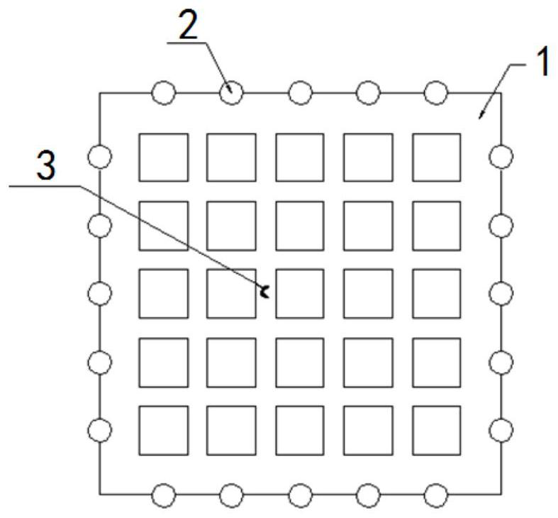
[0029] A liftable grid plate installed in a flocculation tank, such as Figures 1 to 2 As shown in the figure, it includes a grid plate body 1, a roller 2 and a traction rope 3. The grid plate body 1 and the roller 2 are integrally connected, and the grid plate bodies 1 in the same shaft 4 are connected to each other through a traction rope 3, and one end of the traction rope 3 is connected to each other. It is fixed to the grid board body 1, and the other end is connected to the traction device.

[0030] When cleaning is required, the traction device pulls the traction rope 3, and the grid plate body 1 is lifted to the top of the shaft 4 under the action of the traction rope 3 through the action of the roller 2. Take out the grid plate body 1 in the shaft 4 one by one, clean the grid plate body 1, and pull the traction rope 3 to return the grid plate body 1 to the shaft 4 under the action of the roller 2 and the grid plate body 1's own gravity, and clean it. The process is c...

Embodiment 2

[0032] A liftable grid plate installed in a flocculation tank, each grid plate body 1 is surrounded by a plurality of rollers 2, and the rollers 2 are symmetrically arranged on the grid plate body 1, which can improve the stability of the traction process. The rest of the structure is the same as that of Example 1.

Embodiment 3

[0034] A liftable grid plate installed in a flocculation tank, and a guide structure for guiding the up and down movement of the roller 2 is vertically arranged on the inner side of the shaft 4 . The rest of the structure is the same as that of Example 2.


PUM


Abstract

The invention relates to a liftable grid plate installed on a flocculation basin. The liftable grid plate comprises grid plate bodies (1), rollers (2) and traction ropes (3), wherein the rollers (2) and the traction ropes (3) are arranged on the grid plate bodies (1), the grid plate bodies (1) located in the same vertical shaft (4) are connected through the traction ropes (3), and the traction ropes (3) are connected with a traction device. Compared with the prior art, the water supply pool does not need to be stopped and emptied, cleaning is convenient, normal operation of a water plant can be guaranteed, labor input is reduced, and it is guaranteed that the effluent quality stably reaches the standard for a long time.

Description

technical field [0001] The invention relates to the technical field of drinking water treatment, in particular to a liftable grid plate installed in a flocculation tank. Background technique [0002] The main forms of flocculation tanks in the field of drinking water treatment are grid flocculation and folded plate flocculation. Among them, grid flocculation tanks are widely used in large and medium-sized water plants in my country due to their advantages of convenient installation and simple structure. The grid flocculation tank is composed of multi-grid shafts. Several layers of grid plates are installed in each grid shaft, which are staggered up and down to form a series of channels. When the grid passes through the water, a velocity gradient is formed to initiate flocculation. With the passage of time, the flocculated sludge will gradually settle and adhere to the surface of the grid plate, the mesh holes will gradually shrink or even block, the flow velocity of the thro...

Claims


Application Information

Patent Timeline
Patent Type & Authority Applications(China)
IPC IPC(8): C02F1/52
CPCC02F1/5281C02F2303/14
Inventor 王磊夏艺珺严博诚林胜夏沛青张元佳付强者诗怀朱子墨刘新超胡国林高连敬
Owner TONGJI UNIV ARCHITECTURAL DESIGN INST GRP CO LTD
Why Eureka
Try Eureka