Disinfecting, recycling and pretreating device for environment-friendly medical utensils
A pretreatment device and an environmentally friendly technology, which is applied in disinfection, plastic recycling, water supply devices, etc., can solve the problems of potential safety hazards for recyclers, reduced transportation efficiency, and difficult transportation, so as to reduce the frequency of going to and from the hospital and the occupied space. The effect of reducing and reducing the number of contacts
- Summary
- Abstract
- Description
- Claims
- Application Information
AI Technical Summary
Problems solved by technology
Method used
Image
Examples
Embodiment 1
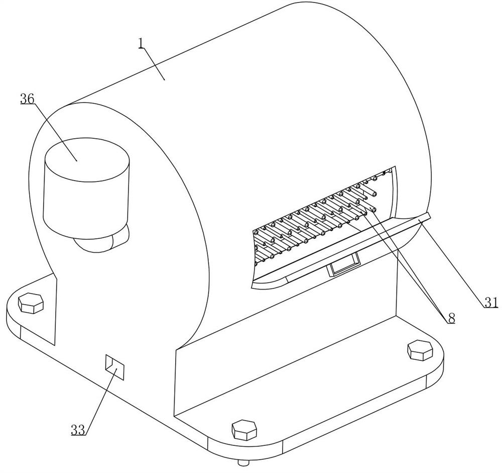
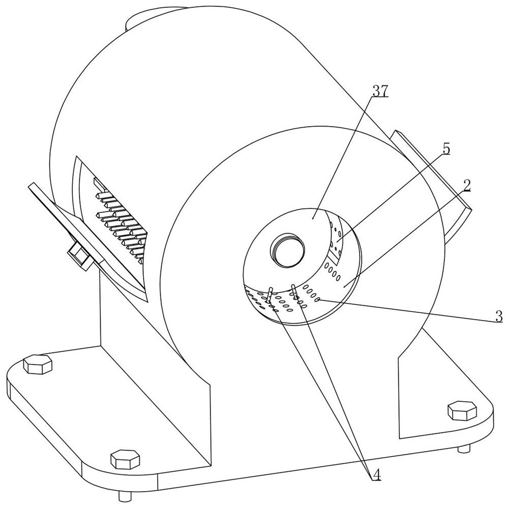
[0031] Embodiment 1, a kind of disinfection recovery pretreatment device of environment-friendly medical vessel, as attached figure 1 As shown, the cylinder 1 is included and the bottom of the cylinder 1 is integrally connected with a base. The improvement of this program is: as attached image 3 As shown, a rotating cylinder 2 is installed coaxially in the cylinder 1 (the rotating cylinder 2 is driven by a micro motor located in the cylinder 1, which is not shown in the figure, and those skilled in the art can arrange the micro motor according to the actual situation. The position of the motor) and the outer wall of the drum 2 is evenly equipped with a number of screen holes 3. When the device is in use, first of all, the device should be installed in a temporary storage place for medical waste infusion bottles 37 and the base should be fixed on the table by screws. On, in order to realize the stability of this device when working;
[0032] The medical staff can collect the ...
Embodiment 2
[0039] Embodiment 2, on the basis of embodiment 1, as attached image 3 As shown, on the axial sides of the bottom wall of the drum 2, two bearing rods 10 (as attached Figure 8 As shown, the length extension direction of the bearing rod 10 is consistent with the length direction of the drum 2, and the bearing rod 10 is set in an L shape) and the needle tubes 4 are all arranged on the bearing rod 10. In this scheme, four bearing rods 10 are arranged uniformly Distributed on both sides of the drum 2 in the axial direction (two bearing rods 10 on each side), the connection between the two bearing rods 10 on the same side is realized through the telescopic rod 11, that is, the two ends of the telescopic rod 11 are respectively connected to the two The bearing rods 10 are fixedly connected, and the two telescopic rods 11 located on both sides of the axial direction are driven by the driving device and driven by the driving device to drive the bearing rods 10 located on both axial ...
Embodiment 3
[0040] Embodiment 3, on the basis of embodiment 2, as attached Figure 7 As shown, how the drive works will be described in detail below:
[0041] A drive motor 14 is fixed coaxially on the drum 2, and the drive motor 14 drives the swing rod 12 coaxially rotated on the drum 2. Initially, the position of the bearing rod 10 relative to the drum 2 is as follows: Figure 10 As shown in , when the drive motor 14 starts, it will drive the swing rod 12 along the Figure 10 Rotate in the clockwise direction shown in , and then through the cooperation of the swing rod 12 and the connecting rod 13, the two T-shaped frames 38 mounted on the rotating drum 2 are driven to move in the direction of approaching each other, as shown in the attached Image 6 As shown, the T-shaped frame 38 is provided with a slotted hole (not labeled in the figure) that is slidingly matched with the telescopic rod 11, and the thicker end of the telescopic rod 11 is slidably fitted with the slotted hole. When ...
PUM
 Abstract
Description
Claims
Application Information
 - R&D
- Intellectual Property
- Life Sciences
- Materials
- Tech Scout
- Unparalleled Data Quality
- Higher Quality Content
- 60% Fewer Hallucinations
Browse by: Latest US Patents, China's latest patents, Technical Efficacy Thesaurus, Application Domain, Technology Topic, Popular Technical Reports.
© 2025 PatSnap. All rights reserved.Legal|Privacy policy|Modern Slavery Act Transparency Statement|Sitemap|About US| Contact US: help@patsnap.com


