
Optical module low-temperature performance testing device

A technology for low-temperature performance and testing equipment, which is applied in measuring equipment, optical instrument testing, and machine/structural component testing, etc. It can solve the problems of easy melting of frost into water droplets and dripping, freezing and jamming of optical modules, and inconvenient removal of optical modules. Release and other issues, to save waiting time, improve test efficiency, and simple structure

Pending Publication Date: 2022-01-04
WUHAN DONGHU UNIV
View PDF0 Cites 0 Cited by
  • Summary
  • Abstract
  • Description
  • Claims
  • Application Information

AI Technical Summary

Problems solved by technology

[0003] When the optical module low-temperature performance test device is working, the moisture inside the air will condense into frost due to the rapid low temperature, and adhere to the inside of the optical module low-temperature performance test device, causing the optical module to freeze and get stuck, making it difficult to take out the optical module. Therefore, when the existing optical module low-temperature performance testing device takes out the optical module, it will be heated for a period of time to facilitate the removal of the optical module. module damage

Method used


Image

  • Optical module low-temperature performance testing device
  • Optical module low-temperature performance testing device
  • Optical module low-temperature performance testing device

Examples


Embodiment Construction

[0029] The following will clearly and completely describe the technical solutions in the embodiments of the present invention with reference to the accompanying drawings in the embodiments of the present invention. Obviously, the described embodiments are only some of the embodiments of the present invention, not all of them. Based on the embodiments of the present invention, all other embodiments obtained by persons of ordinary skill in the art without making creative efforts belong to the protection scope of the present invention.

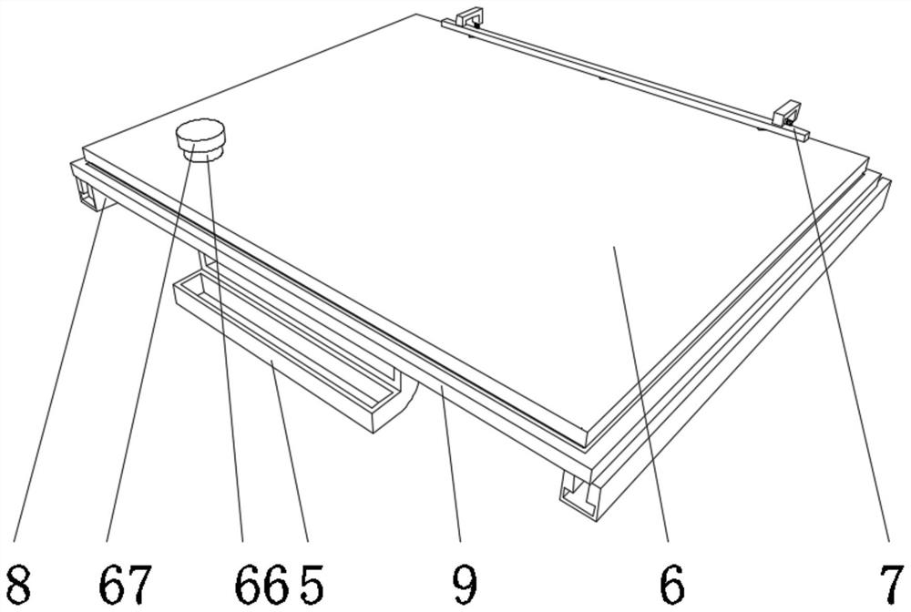
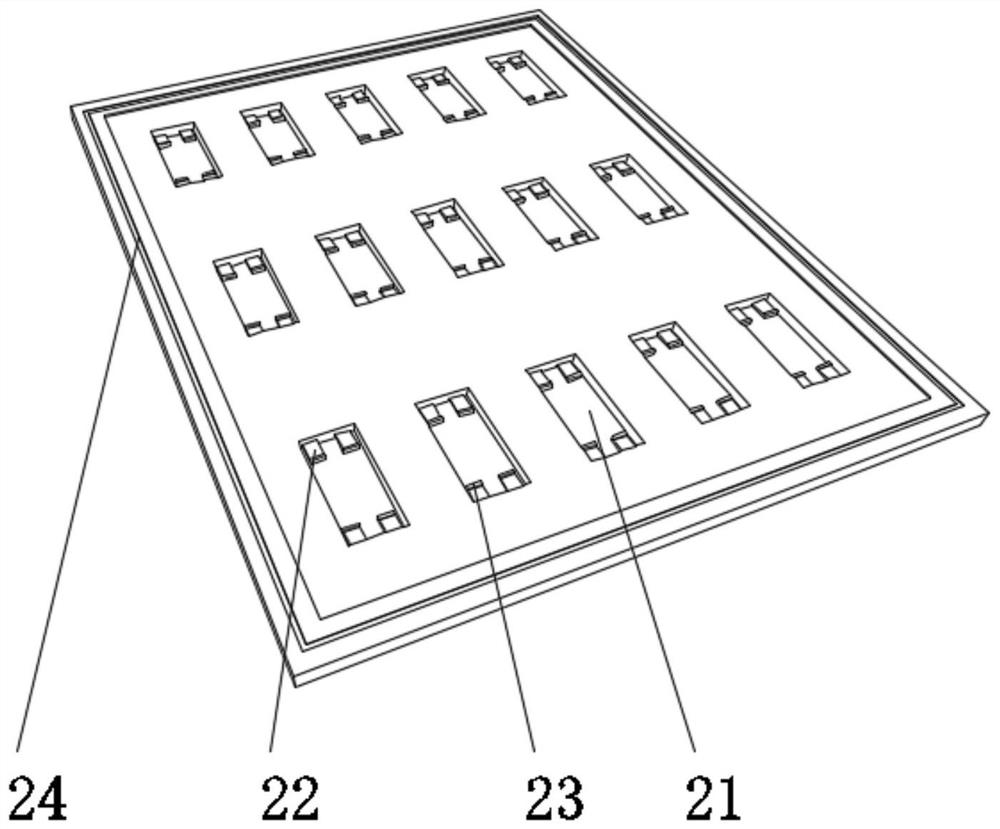
[0030] see Figure 1-Figure 9 As shown, the present invention provides the following technical solutions: a low-temperature performance test device for optical modules, including a high-low temperature aging machine body 1, a storage assembly 2 disposed inside the high-low temperature aging machine body 1, and a cover disposed above the storage assembly 2 6. The storage assembly 2 includes a storage tank 21 and a support block 22 arranged inside ...


PUM


Abstract

An optical module low-temperature performance testing device disclosed by the present invention comprises a high and low-temperature aging machine body, a storage assembly arranged in the high and low-temperature aging machine body and a cover body arranged above the storage assembly, the storage assembly comprises storage grooves and a supporting blocks arranged in the storage grooves, adsorption grooves are formed in the cover body, any two adsorption grooves are connected through a flow channel. The invention specifically relates to the technical field of optical module testing. According to the optical module low-temperature performance testing device, by arranging the cover body, when the high-low temperature aging machine body works, activated carbon is added into the cover body through a feeding port, and then the cover body is elastically shaken through the springs, so that the activated carbon is uniformly distributed in the storage grooves, and the interiors of the storage grooves can be dried; the damage to the optical module caused by frost solidification and frost liquefaction into water is avoided, and meanwhile the problem that the optical module is frozen in the storage grooves and is difficult to take out is solved.

Description

technical field [0001] The invention belongs to the technical field of optical module testing, and in particular relates to an optical module low-temperature performance testing device. Background technique [0002] Optical modules are optoelectronic devices that perform photoelectric and electro-optical conversion. The transmitting end of the optical module converts the electrical signal into an optical signal, and the receiving end converts the optical signal into an electrical signal. Optical modules are classified according to the packaging form, and the common ones are SFP, SFP+, SFF, Gigabit Ethernet Interface Converter (GBIC), etc. [0003] When the optical module low-temperature performance test device is working, the moisture inside the air will condense into frost due to the rapid low temperature, and adhere to the inside of the optical module low-temperature performance test device, causing the optical module to freeze and get stuck, making it difficult to take o...

Claims


Application Information

Patent Timeline
IPC IPC(8): G01M11/00G01M11/04
CPCG01M11/00G01M11/04Y02E10/50
Inventor 刘依
Owner WUHAN DONGHU UNIV
Learn More