
Overhead line system temperature dynamic detection system

A dynamic detection and catenary technology, applied in signal transmission systems, radiation pyrometry, measurement of electricity, etc., can solve the problems of difficult regular observation and judgment, adapting to low vehicle speed, and adapting thermal imagers to low vehicle speed.

Active Publication Date: 2022-01-04
GUANGHAN KE FENG ELECTRONICS CO LTD
View PDF8 Cites 1 Cited by
  • Summary
  • Abstract
  • Description
  • Claims
  • Application Information

AI Technical Summary

Problems solved by technology

Existing methods need to consume a lot of human resources, it is difficult to realize the regular observation and judgment of each clamp position, only key positions can be observed, and there are human misjudgments
Some existing technologies use thermal imaging to detect the temperature at the connection between the catenary and the pantograph catenary. Since the thermal imager is not suitable for high vehicle speeds, it is easy to miss some catenary defects and the temperature measurement error is relatively large.
Other thermal imaging on-board testing equipment is suitable for low speed and large temperature measurement error, so there is no large-scale application

Method used


Image

  • Overhead line system temperature dynamic detection system
  • Overhead line system temperature dynamic detection system
  • Overhead line system temperature dynamic detection system

Examples


Embodiment Construction

[0043] The specific embodiments of the present invention are described below so that those skilled in the art can understand the present invention, but it should be clear that the present invention is not limited to the scope of the specific embodiments. For those of ordinary skill in the art, as long as various changes Within the spirit and scope of the present invention defined and determined by the appended claims, these changes are obvious, and all inventions and creations using the concept of the present invention are included in the protection list.

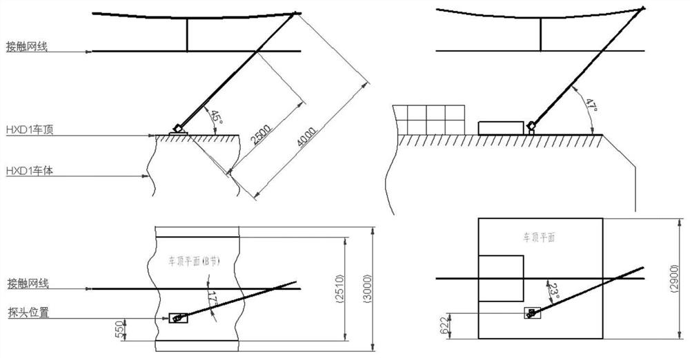
[0044] A catenary temperature dynamic detection system, such as figure 1 As shown, it includes: data acquisition module, image processing module, catenary position identification module, catenary defect comprehensive identification module, monitoring terminal and wireless transmission module, wherein,

[0045] The data collection module is used to obtain infrared imaging data of catenary, high-definition image data and envi...


PUM


Abstract

The invention discloses an overhead line system temperature dynamic detection system. The system comprises a data acquisition module, an image processing module, an overhead line system position identification module, an overhead line system comprehensive defect comprehensive identification module, a monitoring terminal and a wireless transmission module. According to the technical schemes of the system, a high-speed thermal infrared imager and a high-definition visible light camera set are adopted to collect temperature data and image data of an overhead line system, and fault point is pre-judged, and an alarm is given in advance; the fault point is positioned through a positioning system or by accessing TAX data; and early warning information is sent to a ground monitoring terminal through wireless communication, so that analysis and early warning can be carried out. According to an existing overhead line system temperature dynamic detection technology, due to the fact that a thermal imager is not high in adaptation to vehicle speed, overhead line system defects are prone to missing detection, the temperature measurement error is large, and large-area application is not achieved. With the overhead line system temperature dynamic detection system of the invention adopted, the temperature of the overhead line system can be accurately and dynamically measured, and analysis and early warning are conducted on defects.

Description

technical field [0001] The invention relates to the field of power grid detection, in particular to a dynamic detection system for catenary temperature. Background technique [0002] The main conductive circuit of the railway line catenary is composed of power supply lines, return lines, catenary cables, contact lines, hanging strings, connecting lines, etc. The various parts are connected by various clamps, so that this loop extends along the railway, meeting the needs of supplying power to the electric locomotive. The main conductive circuit must be good to ensure the smooth flow of current. If there is a defect, it will cause excessive local current carrying and serious shunting of parts, which will cause local temperature rise of the catenary and burn the catenary equipment. This kind of fault is in the catenary. account for a large proportion of failures. All kinds of connecting wire clips are the weak links in the conductive circuit of the catenary. The contact resis...

Claims


Application Information

Patent Timeline
IPC IPC(8): G01J5/00G01R31/08G08C17/02
CPCG01J5/0096G01R31/085G01R31/088G08C17/02G01J2005/0077
Inventor 郑黄松管孝华黄云吾向东付贤伟曾令仪王佑军梁小俊牟春鹏
Owner GUANGHAN KE FENG ELECTRONICS CO LTD
Learn More