Safe and efficient waste chip cleaning equipment for micro drill bit cutting edge and cleaning method of safe and efficient waste chip cleaning equipment

A technology for micro-drills and cleaning equipment, applied in drilling/drilling equipment, metal processing equipment, maintenance and safety accessories, etc. Avoid a lot of oxidation and rust, facilitate high-precision cleaning, and increase the effect of cleaning range

Active Publication Date: 2022-01-04
悦虎晶芯电路(盐城)有限公司
View PDF9 Cites 1 Cited by
  • Summary
  • Abstract
  • Description
  • Claims
  • Application Information

AI Technical Summary

Problems solved by technology

[0003] The traditional device has the following disadvantages: the existing drill bit does not have the automatic cleaning function, and it cannot quickly clean up the waste debris of the drill bit itself without affecting the drilling process, and it is very easy to damage the drill bit due to waste debris and other residues. Accelerates the oxidation and corrosion of the drill bit, shortens the service life of the drill bit, and at the same time, the existing drill bit cannot lubricate and maintain itself, and cannot maintain its own good operating condition

Method used


Image

  • Safe and efficient waste chip cleaning equipment for micro drill bit cutting edge and cleaning method of safe and efficient waste chip cleaning equipment
  • Safe and efficient waste chip cleaning equipment for micro drill bit cutting edge and cleaning method of safe and efficient waste chip cleaning equipment
  • Safe and efficient waste chip cleaning equipment for micro drill bit cutting edge and cleaning method of safe and efficient waste chip cleaning equipment

Examples


Embodiment Construction

[0033] The following will clearly and completely describe the technical solutions in the embodiments of the present invention with reference to the drawings in the embodiments of the present invention.

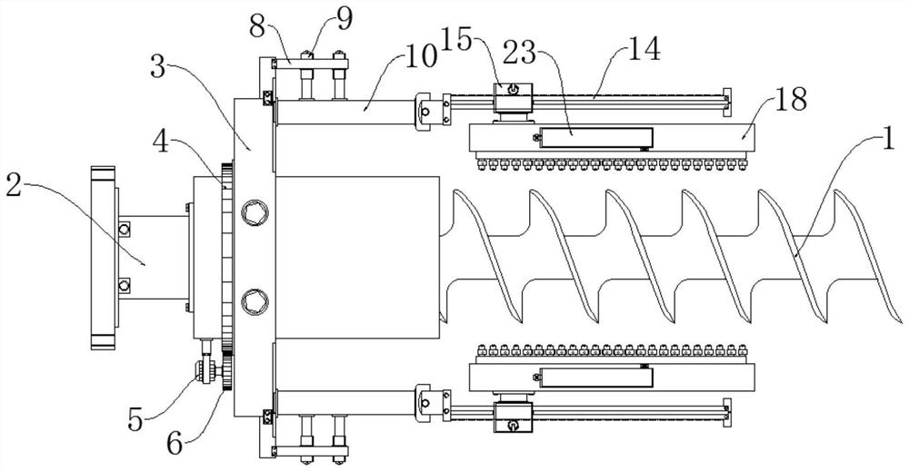
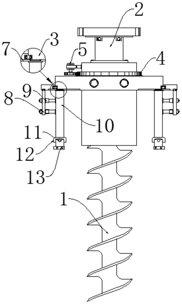
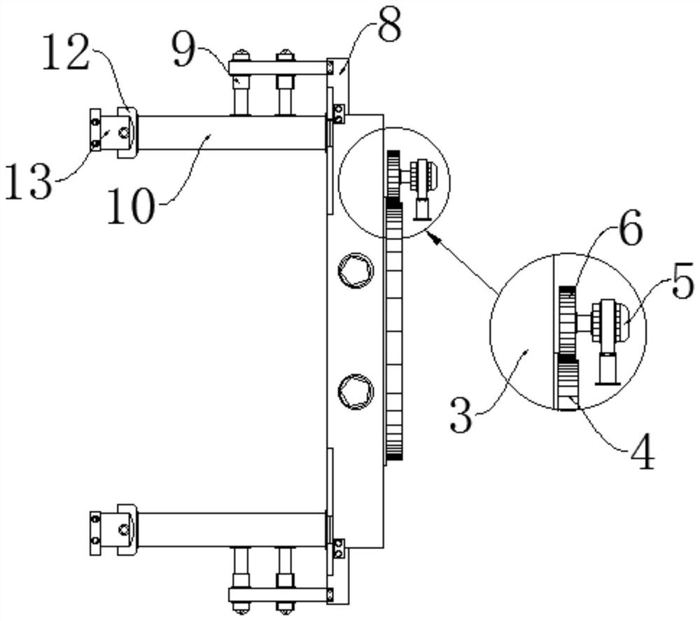
[0034] see Figure 1-7 , the present invention provides a technical solution: a safe and efficient type of waste cleaning equipment for micro drill blades, including a drill body 1, a rotating assembly, two sets of extension assemblies, two sets of lifting assemblies, two sets of injection assemblies and two sets of maintenance Assemblies, the rotating assembly is rotatably installed on the top of the drill body 1, two sets of extension assemblies are symmetrically installed on both sides of the lower surface of the rotating assembly, two sets of lifting assemblies are assembled on the extension assembly, and the injection assembly is installed On one side of the lifting assembly, the maintenance assembly is symmetrically installed on the other side of the lifting assembly.

...


PUM


Abstract

The invention discloses safe and efficient waste chip cleaning equipment for a micro drill bit cutting edge and a cleaning method of the safe and efficient waste chip cleaning equipment. The safe and efficient waste chip cleaning equipment comprises a drill bit body, a rotating assembly, two extending assemblies, two lifting assemblies, two blowing assemblies and two maintaining assemblies, wherein the rotating assembly is rotationally arranged at the top end of the outer portion of the drill bit in a sleeved mode, and the two extending assemblies are symmetrically arranged on the two sides of the lower surface of the rotating assembly. Lubricating liquid is sprayed out through spraying holes, and the surface of the drill bit body is rapidly cleaned, so that the cleanliness of the drill bit body is guaranteed, and the real-time cleaning effect on the drill bit body is achieved. The lubricating liquid is evenly sprayed to the drill bit body through a conveying spraying head, so that the situation that the drill bit body is greatly oxidized, corroded and the like is avoided, and the good working state of the drill bit body is guaranteed. Under cooperation of the extending assemblies and the lifting assemblies, the blowing position can be rapidly adjusted in real time, the cleaning precision of the drill bit is guaranteed, meanwhile, the cleaning direction and the cleaning height can be rapidly and dynamically adjusted and controlled, and operation and use are convenient.

Description

technical field [0001] The invention relates to the related technical field of micro-drills, in particular to a safe and high-efficiency micro-drill waste cleaning device and a cleaning method thereof. Background technique [0002] Drills with a diameter of less than 3.175mm are usually called micro-drills, or micro-drills for short. To make micro-drills work efficiently in use, a series of factors must be considered: such as various elements of the drill itself, processing parameters, hole depth, installation Integrity and the structure of the workpiece, etc., the drill bit has a wide range of applications, and is widely used in various mechanical processing production in daily life. [0003] The traditional device has the following shortcomings: the existing drill bit does not have the automatic cleaning function, and it cannot quickly clean up the waste debris of the drill bit itself without affecting the drilling process, and it is very easy to damage the drill bit due t...

Claims


Application Information

Patent Timeline
IPC IPC(8): B23Q11/00B23Q11/10B23B47/00
CPCB23Q11/005B23Q11/1076B23B47/00B23B2270/28B23B2270/30B23B2270/24Y02P70/10
Inventor 雷森黄治国夏亮
Owner 悦虎晶芯电路(盐城)有限公司
Why Eureka
Try Eureka