Eureka AIR delivers breakthrough ideas for toughest innovation challenges, trusted by R&D personnel around the world.

High-reliability hybrid power supply magnetic device based on exoskeleton structure and manufacturing method thereof

A magnetic device and hybrid power supply technology, applied in the direction of electrical components, circuits, magnetic core/yoke, etc., can solve the problem of cracks on the side of the magnetic core, material strength and structure that cannot meet high mechanical stress, and limited strength of ferrite magnetic materials and other problems, to achieve the effect of small installation area

Active Publication Date: 2021-12-31
NO 24 RES INST OF CETC
View PDF9 Cites 0 Cited by
  • Summary
  • Abstract
  • Description
  • Claims
  • Application Information

AI Technical Summary

Problems solved by technology

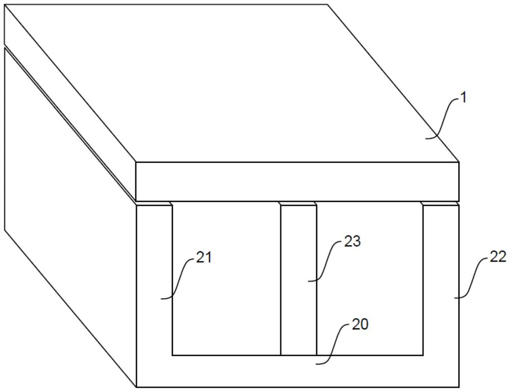
The ER18 planar magnetic core is composed of two parts: the upper magnetic core of the flat shape and the lower magnetic core of the E shape. The strength of the TP5 ferrite magnetic material is limited. 1mm, the material is relatively thin, and cannot meet the requirements of high mechanical stress in terms of material strength and structure
After the mechanical test, cracks appeared on the side of the magnetic core, which affected the electrical parameters and circuit reliability, did not meet the requirements of aerospace high-reliability applications, and became a weak link in the interconnection structure of high-power hybrid power supplies

Method used


Image

  • High-reliability hybrid power supply magnetic device based on exoskeleton structure and manufacturing method thereof
  • High-reliability hybrid power supply magnetic device based on exoskeleton structure and manufacturing method thereof
  • High-reliability hybrid power supply magnetic device based on exoskeleton structure and manufacturing method thereof

Examples


Embodiment Construction

[0032] Embodiments of the present invention are described below through specific examples, and those skilled in the art can easily understand other advantages and effects of the present invention from the content disclosed in this specification. The present invention can also be implemented or applied through other different specific implementation modes, and various modifications or changes can be made to the details in this specification based on different viewpoints and applications without departing from the spirit of the present invention. It should be noted that the diagrams provided in the following embodiments are only schematically illustrating the basic concept of the present invention, and the following embodiments and the features in the embodiments can be combined with each other in the case of no conflict.

[0033] In a preferred embodiment of the high-reliability hybrid power magnetic device based on the exoskeleton structure of the present invention, the magneti...


PUM

PropertyMeasurementUnit
thicknessaaaaaaaaaa
thicknessaaaaaaaaaa
thicknessaaaaaaaaaa

Abstract

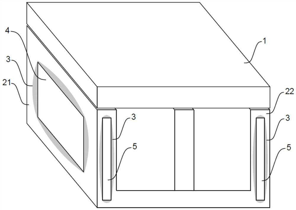
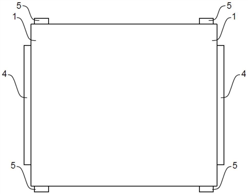
The invention relates to a high-reliability hybrid power supply magnetic device based on exoskeleton structures. The exoskeleton structures are arranged on a left side plate and a right side plate of a lower magnetic core; each exoskeleton structure comprises first skeleton ceramic chips which are fixedly adhered to the left side surface of the left side plate and the right side surface of the right side plate, and second skeleton ceramic chips which are fixedly adhered to the front side surfaces and the rear side surfaces of the left side plate and the right side plate; the areas of the first skeleton ceramic chips and the second skeleton ceramic chips are smaller than the areas of the corresponding side surfaces; the thermal expansion coefficient of the first skeleton ceramic chips and the thermal expansion coefficient of the second skeleton ceramic chips are matched with the thermal expansion coefficient of the lower magnetic core. According to the invention, by adding the exoskeleton structures, the magnetic device can meet the working requirements in a space navigation environment, and still meet the deflation test requirements; in addition, after the exoskeleton structures are added to the magnetic device, the overall installation area change is small, and the magnetic device can be suitable for a miniaturized hybrid integrated circuit with a limited installation range.

Description

technical field [0001] The invention belongs to the technical field of aerospace high-reliability hybrid power supplies, and relates to a high-reliability hybrid power supply magnetic device based on an exoskeleton structure and a manufacturing method thereof. Background technique [0002] High-reliability and high-power hybrid power supplies for aerospace require high resistance to mechanical stress, and the magnetic devices (transformers, inductors) used inside must have sufficiently high saturation magnetic induction density and low loss to meet high-power, high-current requirements. And the requirements of electrical parameters, but also need to meet the limited installation space and high mechanical stress resistance requirements, so the magnetic device is made of ER18 planar magnetic core made of TP5 or TPW33 ferrite material. The ER18 planar magnetic core is composed of two parts: the upper magnetic core of the flat shape and the lower magnetic core of the E shape. Th...

Claims


Application Information

Patent Timeline
Patent Type & Authority Applications(China)
IPC IPC(8): H01F3/00
CPCH01F3/00
Inventor 肖玲向敏罗驰燕子鹏
Owner NO 24 RES INST OF CETC
Why Eureka
Eureka Blog
Learn More