
Water vapor loop constant pressure control method and device for extracorporeal shock wave machine

An extracorporeal shock wave and constant pressure control technology, applied in electric fluid pressure control, medical science, surgery, etc., can solve problems such as high cost, cumbersome operation, and inability to be used in practice, and achieve accurate pressure conduction, electrical Simple control system

Pending Publication Date: 2021-12-31
上海精诚医疗科技有限公司
View PDF1 Cites 0 Cited by
  • Summary
  • Abstract
  • Description
  • Claims
  • Application Information

AI Technical Summary

Problems solved by technology

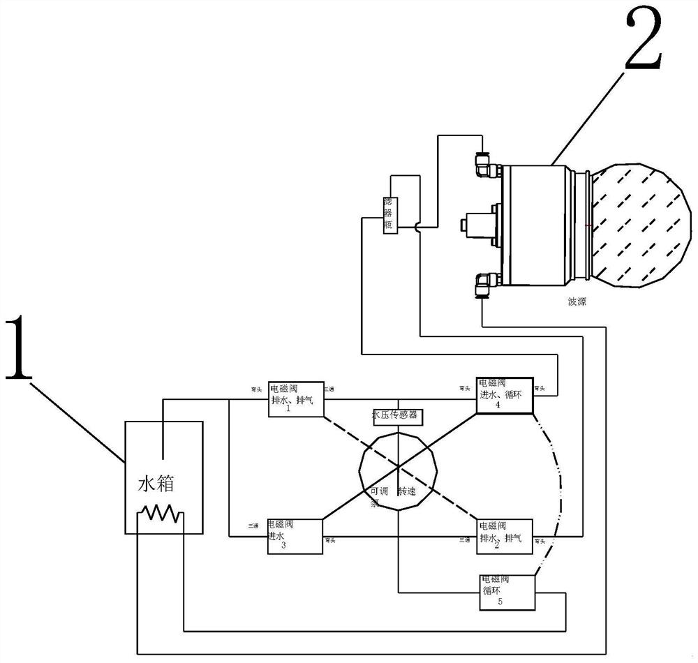
[0002] At present, most of the extracorporeal shock wave machines are still in manual positioning, which is cumbersome, time-consuming and labor-intensive, and the operation is too complicated when the automatic control is mature, and in actual life, the focus and the treatment field are not overlapped to achieve accurate positioning , the current so-called automatic positioning is to find the distance from the human epidermis to the treatment area through B-ultrasound, and then send the measured data to the positioning system. But usually, the water bladder wraps the focal point. At this time, if the focus is moved to the two positions measured by the B-ultrasound, the water bladder will inevitably squeeze the human body, and the previous treatment area will be displaced. The final result is that the focus and the treatment area do not coincide. , cannot be really used in practice, and the combination of different doctors, different patients such as the elderly, the weak, the sick and the disabled, and the severity of the disease will give patients a worse experience, and doctors also have operational risks. Existing countries The patent online publication number is CN111407360A, an invention of a water vapor circuit constant pressure control method and device for an extracorporeal shock wave machine (see the accompanying drawings figure 1 ), but it still has the following disadvantages:
[0003] 1. When moving the focus of the wave source to the position of the stone measured by the B-ultrasound, due to the absence of a constant pressure system, the water bladder squeezes the human body, resulting in a displacement of the stone position currently measured by the B-ultrasound
[0004] 2. Squeeze the patient, there is a certain risk of crushing the patient, and the user experience is poor
[0005] 3. The precise electronic control system capable of achieving constant voltage is expensive and the software control is complex

Method used


Image

  • Water vapor loop constant pressure control method and device for extracorporeal shock wave machine
  • Water vapor loop constant pressure control method and device for extracorporeal shock wave machine
  • Water vapor loop constant pressure control method and device for extracorporeal shock wave machine

Examples


Embodiment 1

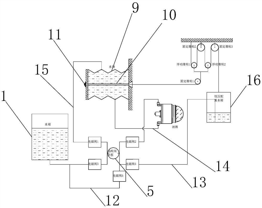
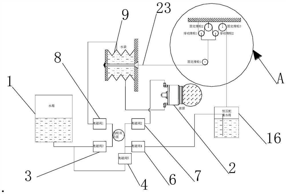
[0028] S1. First, inject an appropriate amount of water into the main water tank 1, the water bag 9 and the constant pressure counterweight water tank 16;

[0029] S2. Close solenoid valve three 3, solenoid valve five 4, solenoid valve four 5, solenoid valve two 7 and solenoid valve one 8, so that the constant pressure counterweight water tank 16 passes through the pulley device, and the pressure of 1:4 is transmitted to make the control The thread 23 is tightened, and the water bag 9 is squeezed, so that the water in the water bag 9 enters the wave source 2, so that the water bag expands;

[0030]S3. By opening solenoid valve 2 7 and solenoid valve 1 8, closing the other solenoid valves, turning on the gear bidirectional pump 6 and making the water flow direction from right to left, forming a water circulation system, in this cycle, the gas inside the wave source 2 will also be automatically discharged;

[0031] S4. By opening solenoid valve one 8 and solenoid valve five 4, ...

Embodiment 2

[0034] S1. First, inject an appropriate amount of water into the main water tank 1, the water bag 9 and the constant pressure counterweight water tank 16;

[0035] S2. Close solenoid valve three 3, solenoid valve five 4, solenoid valve four 5, solenoid valve two 7 and solenoid valve one 8, so that the constant pressure counterweight water tank 16 passes through the pulley device, and the pressure of 1:4 is transmitted to make the control The thread 23 is tightened, and the water bag 9 is squeezed, so that the water in the water bag 9 enters the wave source 2, so that the water bag expands;

[0036] S3. By opening solenoid valve 2 7 and solenoid valve 1 8, closing the other solenoid valves, turning on the gear bidirectional pump 6 and making the water flow direction from right to left, forming a water circulation system, in this cycle, the gas inside the wave source 2 will also be automatically discharged;

[0037] S4. By opening solenoid valve one 8 and solenoid valve five 4,...


PUM


Abstract

The invention relates to the technical field of extracorporeal shock wave treatment equipment in medical instruments, and discloses a water vapor loop constant pressure control method and device for an extracorporeal shock wave machine. The device comprises a main water tank body, a wave source, a third electromagnetic valve, a fifth electromagnetic valve, a fourth electromagnetic valve, a gear two-way pump, a second electromagnetic valve, a first electromagnetic valve, a water bag, a constant-pressure balance weight water tank body, a third fixed pulley, a second fixed pulley, a second floating pulley, a first floating pulley and a first fixed pulley, the main water tank body is vertically arranged, and the bottom of the main water tank body is connected with a connecting pipe in a penetrating mode. According to the water vapor loop constant pressure control method and device for the extracorporeal shock wave machine, an electric control system is simple, and the functions of water feeding, water discharging, water circulating and air exhausting can be easily achieved only by controlling the water feeding direction of one gear two-way pump and the switch combination of the electromagnetic valves; and the constant-pressure counterweight water tank body is utilized to extrude the water bag through 1:4 pressure conduction through a pulley device, so that constant pressure is perfectly realized, and the pressure conduction is more accurate.

Description

technical field [0001] The invention relates to the technical field of extracorporeal shock wave therapy equipment in medical devices, in particular to a constant pressure control method and device for a water vapor circuit of an extracorporeal shock wave machine. Background technique [0002] At present, most of the extracorporeal shock wave machines are still in manual positioning, which is cumbersome, time-consuming and labor-intensive, and the operation is too complicated when the automatic control is mature, and in actual life, the focus and the treatment field are not overlapped to achieve accurate positioning , the current so-called automatic positioning is to find the distance from the human epidermis to the treatment area through B-ultrasound, and then send the measured data to the positioning system. But usually, the water bladder wraps the focal point. At this time, if the focus is moved to the two positions measured by the B-ultrasound, the water bladder will ine...

Claims


Application Information

Patent Timeline
Patent Type & Authority Applications(China)
IPC IPC(8): A61B17/225G05D16/20
CPCA61B17/225A61B17/2256G05D16/20A61B2017/00017
Inventor 赵研文刘同关钱余运吴进钱勇
Owner 上海精诚医疗科技有限公司
Learn More