Gas-liquid two-phase flow field three-dimensional reconstruction system based on laser scanning

A technology of 3D reconstruction and laser scanning, which is applied in the direction of flow characteristics, image data processing, and measurement devices, can solve the problems of fluorescence intensity influence, dependence, and inability to obtain flow structure at the same time, and achieve high temporal and spatial resolution while low spatial resolution Effect

Pending Publication Date: 2021-12-28
TIANJIN UNIV
View PDF0 Cites 0 Cited by
  • Summary
  • Abstract
  • Description
  • Claims
  • Application Information

AI Technical Summary

Problems solved by technology

BBLIF is a detection method based on the relationship between the local intensity of the excited fluorescence and the local thickness of the liquid film. The main disadvantage is that it depends on the laser intensity, so the stability of the laser and the non-uniform intensity distribution on the illuminated area need to be considered. In addition, the concentration of the fluorescent dye and Temperature also has a greater effect on the fluorescence intensity
The fluorescence image collected in the PLIF technique is a cross-sectional image of the flow field, and the boundary of the flow structure can be determined only by spatially calibrating the image, so it is less affected by the laser intensity, temperature and dye concentration, but it cannot Simultaneously obtain flow structure in both direction and circumferential direction
At present, none of them can be applied to the 3D reconstruction of the flow structure of gas-liquid two-phase flow

Method used


Image

  • Gas-liquid two-phase flow field three-dimensional reconstruction system based on laser scanning
  • Gas-liquid two-phase flow field three-dimensional reconstruction system based on laser scanning
  • Gas-liquid two-phase flow field three-dimensional reconstruction system based on laser scanning

Examples


Embodiment Construction

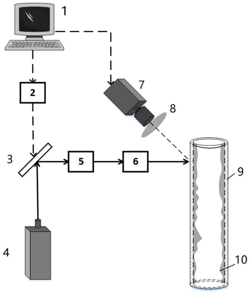
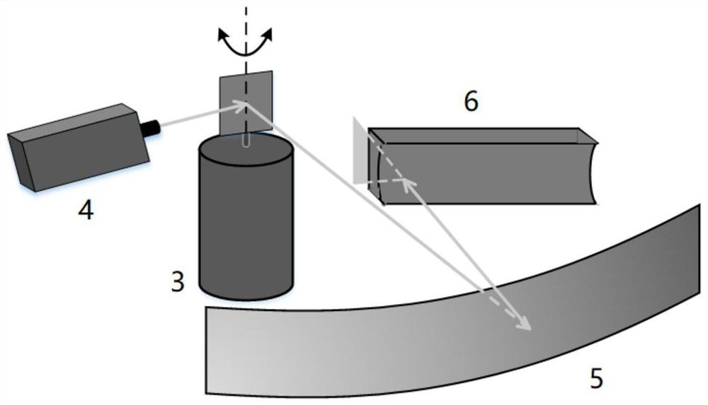
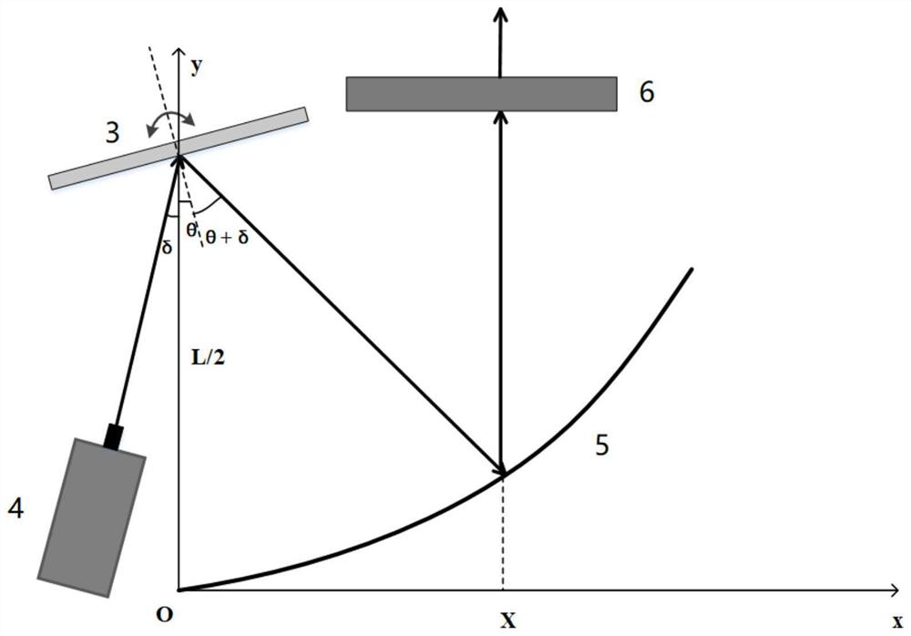
[0030] The three-dimensional reconstruction system of the gas-liquid two-phase flow field based on laser scanning of the present invention includes a computer (1), a vibrating mirror controller (2), a vibrating mirror (3), a laser (4), and a parabolic reflector L1 (5) , plano-concave cylindrical lens L2 (6), high-speed camera (7), optical filter F1 (8), measuring pipeline (9) and gas-liquid two-phase flow (10).

[0031] During specific implementation, the laser (4) selects a continuous laser with a wavelength of 532nm. The measuring pipe (9) is transparent and made of acrylic material, the liquid phase of the gas-liquid two-phase flow (10) in the measuring pipe (9) is added with fluorescent substance rhodamine B, and the lens of the high-speed camera (7) is equipped with a long-wavelength sensor with a wavelength of 570nm. pass filter (8).

[0032] During specific implementation, the computer (1) is connected to the vibrating mirror controller (2) and the high-speed camera (7...


PUM

PropertyMeasurementUnit
wavelengthaaaaaaaaaa

Abstract

The invention relates to a gas-liquid two-phase flow field three-dimensional reconstruction system based on laser scanning, which comprises a computer, a galvanometer controller, a galvanometer, a laser, a parabolic reflector, a plano-concave cylindrical lens, a high-speed camera and a transparent measuring pipeline. Fluorescent substances are added in the liquid phase of the gas-liquid two-phase flow passing through the measuring pipeline, the parabolic reflector is used for parallelizing deflected laser beams reflected by the center of the galvanometer lens; and the plano-concave cylindrical lens is used for expanding the laser beam into sheet laser. The centers of the galvanometer lens, the parabolic reflector and the plano-concave cylindrical lens are located on the same light path, the parabolic reflector is in a parabola shape in the laser scanning direction, and the generatrix of the plano-concave cylindrical lens is parallel to the laser scanning direction; fluorescent light generated by the gas-liquid two-phase flow through laser irradiation is collected by a high-speed camera through an optical filter; and the computer processes the slice image acquired by the high-speed camera to realize three-dimensional reconstruction of the gas-liquid two-phase flow flowing structure.

Description

technical field [0001] The invention belongs to the field of three-dimensional measurement of gas-liquid two-phase flow, in particular to a three-dimensional reconstruction system of gas-liquid two-phase flow flow field based on laser scanning. Background technique [0002] Gas-liquid two-phase flow is a two-phase flow system composed of a mixture of gas and liquid. It is widely used in industrial processes such as chemical industry, power, smelting and atomic energy. function, mathematical description difficulties and other characteristics. Accurately measuring the flow characteristics of gas-liquid two-phase flow is of great significance for monitoring flow conditions and heat and mass transfer characteristics, ensuring production safety and improving production efficiency. Most of the existing gas-liquid two-phase flow detection technologies are one-dimensional or two-dimensional measurement technologies, which can only detect the flow field at certain positions or direc...

Claims


Application Information

Patent Timeline
Patent Type & Authority Applications(China)
IPC IPC(8): G01N11/00G06T7/00
CPCG01N11/00G06T7/0002
Inventor 薛婷安梦蕊吴斌
Owner TIANJIN UNIV
Why Eureka
Try Eureka