
Aircraft test fresh air control system and control method

A control system and control method technology, applied in the direction of aircraft component testing, etc., can solve the problems that cannot meet the needs of aircraft engine tests, etc., and achieve the effects of uniform and stable supply, stable temperature, and high control accuracy

Active Publication Date: 2021-12-28
CHINA AIRPLANT STRENGTH RES INST
View PDF7 Cites 2 Cited by
  • Summary
  • Abstract
  • Description
  • Claims
  • Application Information

AI Technical Summary

Problems solved by technology

[0005] The technical problem solved by the present invention is: the existing technology cannot meet the needs of my country's aircraft laboratory for aircraft engine testing under extremely low temperature conditions

Method used


Image

  • Aircraft test fresh air control system and control method
  • Aircraft test fresh air control system and control method
  • Aircraft test fresh air control system and control method

Examples


Embodiment 1

[0078] This embodiment is an aircraft test fresh air control system, comprising:

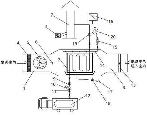
[0079] gas subsystem, such as figure 1 As shown, the supplementary air subsystem includes: a compensation air duct 1 for introducing outdoor air into the aircraft climate laboratory, a liquid nitrogen heat exchanger 2 connected with the compensation air duct 1 for cooling the outdoor air, and a liquid nitrogen heat exchanger 2 connected with the liquid nitrogen The heat exchanger 2 is connected to the air supply duct 3 for sending low-temperature air into the room. The air supply duct 3 is located outside the aircraft climate laboratory and communicates with the aircraft climate laboratory. The air supply duct 3 is provided with a damper 13, which also The control module located in the aircraft climate laboratory with local manual control and remote automatic control functions, the temperature monitoring module for monitoring the temperature of the supply air, the humidity monitoring module for ...

Embodiment 2

[0089] This embodiment is a method for controlling fresh air in aircraft tests based on Embodiment 1, such as Figure 8 shown, including the following steps:

[0090] S1. Before the test starts, the control system is powered on, and the liquid nitrogen inlet switch valve 11 and the nitrogen discharge switch valve 19 are opened;

[0091] S2, docking the liquid nitrogen tanker 12 with the liquid nitrogen heat exchanger 2, and adjusting the supply pressure of the liquid nitrogen tanker 12 to 4 Bar;

[0092] S3, start the nitrogen dilution fan 8;

[0093] S4. The tester's mobile device is connected to the system through the wireless networking sub-module, and then the temperature setting sub-module is used to set the compensation air temperature target value , the PLC controller controls the frequency conversion compensation fan 5 to start at a low speed, and obtains the fresh air temperature at the outlet of the liquid nitrogen heat exchanger 2 through the temperature sensor a...


PUM


Abstract

The invention provides an aircraft test fresh air control system and control method and relates to the technical field of aircraft test. The aircraft test fresh air control system comprises an air supply subsystem, wherein the air supply subsystem comprises a compensation air duct, a liquid nitrogen heat exchanger and an air supply pipeline. The aircraft test fresh air control method comprises the following steps of S1, before a test is started, a control system being powered on; S2, the liquid nitrogen tank car and the liquid nitrogen heat exchanger being in butt joint; S3, starting a nitrogen dilution fan; S4, an air temperature target value being set and regulated; S5, air supply and exhaust balance being kept; S6, determining that the liquid nitrogen heat exchanger is frosted and defrosted; S7, further testing; S8, prompting and alarming when the liquid nitrogen tank car needs to be replaced; and S9, completing the test. According to the method, a problem that the prior art cannot meet the test requirements of an aircraft laboratory on the whole engine of an aircraft under the condition of extremely low temperature is solved, and the method has advantages of real-time flow monitoring and PID / Bang-Bang combined temperature control.

Description

technical field [0001] The invention relates to the technical field of aircraft testing, in particular to an aircraft testing fresh air control system and a control method. Background technique [0002] In order to give full play to the combat effectiveness of weapons and equipment, it is necessary to test the environmental adaptability requirements and evaluation index system of military aircraft to make it better adapt to the complex and diverse environments of our country. [0003] Especially the aircraft test in extremely low temperature environment is essential. In a low-temperature environment, ice tends to accumulate on the leading edge of the wings and tail of the aircraft, resulting in deformation, resulting in reduced lift and increased drag. Ice accumulation in the dynamic and static pressure holes of the aircraft will cause instrument distortion and affect the pilot's judgment. After the impact, it may directly cause an aircraft crash and cause casualties. There...

Claims


Application Information

Patent Timeline
Patent Type & Authority Applications(China)
IPC IPC(8): B64F5/60
CPCB64F5/60
Inventor 王彬文吴敬涛成竹杜文辉李闯勤
Owner CHINA AIRPLANT STRENGTH RES INST
Learn More