
Prestressed concrete slab girder bridge type and construction method thereof

A prefabricated concrete slab and construction method technology, applied in bridges, bridge materials, bridge construction, etc., can solve problems such as affecting the normal operation of bridges, existing safety hazards, and poor economic benefits, reducing the amount of formwork and concrete, and improving construction. Efficiency, improved safety and durability

Active Publication Date: 2021-12-24
NANJING UNIV OF SCI & TECH
View PDF12 Cites 0 Cited by
  • Summary
  • Abstract
  • Description
  • Claims
  • Application Information

AI Technical Summary

Problems solved by technology

At present, there are two common construction methods for small and medium-span concrete bridges: one is the reinforced concrete assembled hinged girder bridge, that is, the main girder is prefabricated in the factory, and the adjacent main girders are connected by wet joints on site. It is easy to be damaged under the action of heavy-duty vehicles, resulting in stress on the single beam, affecting the normal operation of the bridge, and posing safety hazards
The other is the cast-in-place reinforced concrete integral girder bridge, through the cast-in-place reinforced concrete bridge deck, the effective bonding between the prefabricated beam and the cast-in-place layer is realized; this kind of integral bridge has good mechanical properties and avoids damage at wet joints , but requires a large amount of on-site steel binding and concrete pouring workload, prolonging the construction period and poor economic benefits

Method used


Image

  • Prestressed concrete slab girder bridge type and construction method thereof
  • Prestressed concrete slab girder bridge type and construction method thereof
  • Prestressed concrete slab girder bridge type and construction method thereof

Examples


Embodiment Construction

[0031] The present invention will be further introduced below in conjunction with the accompanying drawings and specific embodiments.

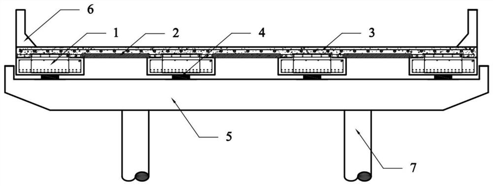
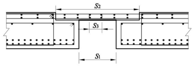
[0032] combine Figure 1-Figure 10 , a prestressed concrete slab girder bridge suitable for rapid construction, which has two main girder construction connection methods, that is, according to the size of the clear distance between adjacent main girders, the pre-embedded connection steel bars can be selected to overlap or the precast concrete slab connection can be selected , the former is suitable for smaller girder spacing, and the latter is used for larger girder spacing. The main components include inverted T-shaped main girder 1, prefabricated concrete slab 2, and cast-in-place reinforced concrete deck 3; main girder 1 is the key structural component to bear the load, and the on-site formwork or shelving is selected according to the net distance of the main girder in the actual bridge example The prefabricated concrete slab 2 is used to ...


PUM


Abstract

The invention discloses a prestressed concrete slab girder bridge type and a construction method thereof. The prestressed concrete slab girder bridge type comprises the following components: a support which is arranged on a cover beam and is used for supporting prestressed concrete girders; the prestressed concrete girders which serve as a main bearing component and are in an inverted T shape, wherein the two ends of the prestressed concrete girder are placed on the support, and the upper surface of the prestressed concrete girder is covered with a cast-in-place reinforced concrete bridge deck, wherein the adjacent prestressed concrete girders are in lap joint through embedded connecting steel bars or connected through prefabricated concrete slabs, and the protruding steps of the prestressed concrete girders are filled and leveled up. According to a bridge example with a small clear distance between girders, connection between the prefabricated girders is achieved by lap joint of connecting steel bars of the adjacent girders and overall cast-in-place of bridge deck slabs; and for a bridge example with a large girder spacing, the use amount of templates required by cast-in-place of the bridge deck can be reduced by adopting the precast concrete slab, and the construction efficiency is further improved.

Description

technical field [0001] The invention belongs to the technical field of bridges, in particular to a type of prestressed concrete slab girder bridge and a construction method thereof. Background technique [0002] Since the end of the 20th century, my country's highway and bridge construction has developed rapidly. As of 2020, there are 764,000 small and medium-span bridges on expressways across the country, accounting for nearly 90%. Common structural forms include hollow slab bridges, T-beam bridges and small boxes. girder bridge. Existing investigations and studies have found that hollow slab girder bridges have problems such as hinge cracking and damage, longitudinal and transverse cracking at the bottom of the slab, and concrete spalling; T-shaped girder bridges are difficult to control the quality of wet joint reinforcement connections during construction, often causing quality problems; small Box girder bridges often have reinforcement leaks due to too small thickness o...

Claims


Application Information

Patent Timeline
Patent Type & Authority Applications(China)
IPC IPC(8): E01D1/00E01D2/00E01D21/00E01D19/12E01D19/06E01D101/28
CPCE01D1/00E01D2/00E01D21/00E01D19/125E01D19/067E01D2101/28
Inventor 蒋学峰蒋冬启范进陈雪琴孙晓梅
Owner NANJING UNIV OF SCI & TECH
Learn More