Connecting method and connecting device for materials with different diameters
A connecting device and small-diameter technology, which is applied in the direction of buildings, building reinforcements, building components, etc., can solve the problems that the tensile strength and shear force of the connection position cannot meet the structure and design requirements, and materials with different diameters cannot be connected, etc., to achieve The effect of saving construction materials, simple structure and easy operation
- Summary
- Abstract
- Description
- Claims
- Application Information
AI Technical Summary
Problems solved by technology
Method used
Image
Examples
Embodiment 1
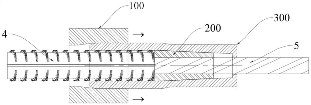
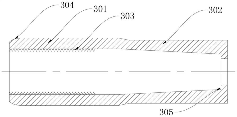
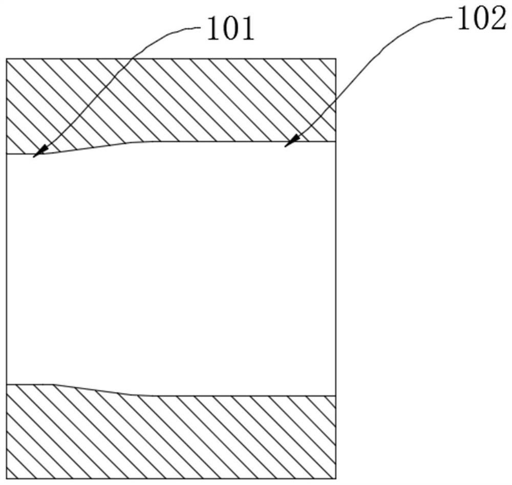
[0036] Embodiment 1: as Figure 1 to Figure 6As shown, the present invention provides a connection device for materials with different diameters, the large diameter material is a hot-rolled ribbed steel bar 4, the small diameter material is a prestressed concrete steel bar 5, and the connection device is used to connect the hot-rolled ribbed steel bar 4 It is connected with the prestressed concrete steel rod 5, and also meets the tension requirement of the prestressed concrete steel rod 5. The connecting device includes a connecting sleeve 300, a locking piece 200 and a diameter-reducing sleeve 100. The connecting sleeve 300 has an inner hole penetrating axially, one end of which is an equal-diameter end 301 with a constant inner diameter, and the other end is an end with a reduced inner diameter. Reduced-diameter end 302, the inner diameter of the equal-diameter end 301 is greater than the outer diameter of the hot-rolled ribbed steel bar 4 to be connected, and the inner hole...
Embodiment 2
[0039] Example 2, such as Figure 7 and Figure 8 As shown, the others are the same as in Embodiment 1, the difference is that the locking piece 200 is formed by opening a number of deformation grooves 204 along the axis on the inner wall of the conical cylinder 205, and the deformation grooves 204 are not seriously dug through in the radial direction. , so the locking piece 200 is still a tapered cylinder 205 as a whole, and the dug out part provides space for the radial compression deformation of the locking piece 200 .
[0040] It should be noted that the inner wall of the connecting sleeve 300 of the present invention can be a plane or a rough surface composed of a large number of protrusions or grooves, and the specific shape is not limited. When the connecting sleeve 300 is deformed, the rough surface can generate enough static friction to The connecting sleeve 300 is connected with the hot-rolled ribbed steel bar 4 together.
[0041] It should be noted that the materi...
Embodiment 3
[0042] Embodiment 3, other parts are identical with embodiment 1, as figure 2 , 5 As shown, the difference is that: the inner wall of the equal-diameter end 301 of the connecting sleeve 300 is processed into internal threads 303 or several annular grooves; the inner wall of the integral tapered cylinder 205 is processed into internal threads 203 or several annular grooves, The outer wall of the tapered cylinder 205 is provided with a taper matching the reduced-diameter end 302 of the connecting sleeve 300 , and the center of the tapered cylinder 205 is provided with a connecting shaft hole 206 whose diameter is slightly larger than the outer diameter of the prestressed concrete steel rod 5 . Through the internal thread setting, the bite ability is increased, the connection strength is improved, and the driving force for driving the reducing sleeve is reduced.
[0043] In use, when the reducing sleeve 100 passes through the equal-diameter end 301, the connecting sleeve 300 is...
PUM
 Abstract
Description
Claims
Application Information
 - R&D
- Intellectual Property
- Life Sciences
- Materials
- Tech Scout
- Unparalleled Data Quality
- Higher Quality Content
- 60% Fewer Hallucinations
Browse by: Latest US Patents, China's latest patents, Technical Efficacy Thesaurus, Application Domain, Technology Topic, Popular Technical Reports.
© 2025 PatSnap. All rights reserved.Legal|Privacy policy|Modern Slavery Act Transparency Statement|Sitemap|About US| Contact US: help@patsnap.com


