
Optical cable detection equipment, system and method

A detection equipment and optical cable technology, which is applied in the field of optical cable detection, can solve the problems of potential safety hazards and low efficiency in troubleshooting fault points, and achieve the effect of improving detection efficiency

Active Publication Date: 2021-12-17
CHINA UNITED NETWORK COMM GRP CO LTD
View PDF8 Cites 2 Cited by
  • Summary
  • Abstract
  • Description
  • Claims
  • Application Information

AI Technical Summary

Problems solved by technology

[0004] However, most optical cable faults occur on communication towers. Maintenance personnel determine the fault point through high-altitude operations. The efficiency of troubleshooting the fault point is low, and there are potential safety hazards

Method used


Image

  • Optical cable detection equipment, system and method
  • Optical cable detection equipment, system and method
  • Optical cable detection equipment, system and method

Examples


Embodiment Construction

[0054] The following will clearly and completely describe the technical solutions in the embodiments of the present invention with reference to the accompanying drawings in the embodiments of the present invention. Obviously, the described embodiments are only some, not all, embodiments of the present invention. Based on the embodiments of the present invention, all other embodiments obtained by persons of ordinary skill in the art without making creative efforts belong to the protection scope of the present invention.

[0055] The terms "comprising" and "having" in the description and claims of the present invention and the above drawings, as well as any variations thereof, are intended to cover non-exclusive inclusion, for example, processes, methods, A system, product or device is not necessarily limited to those steps or elements explicitly listed, but may include other steps or elements not explicitly listed or inherent to the process, method, product or device.

[0056] ...


PUM


Abstract

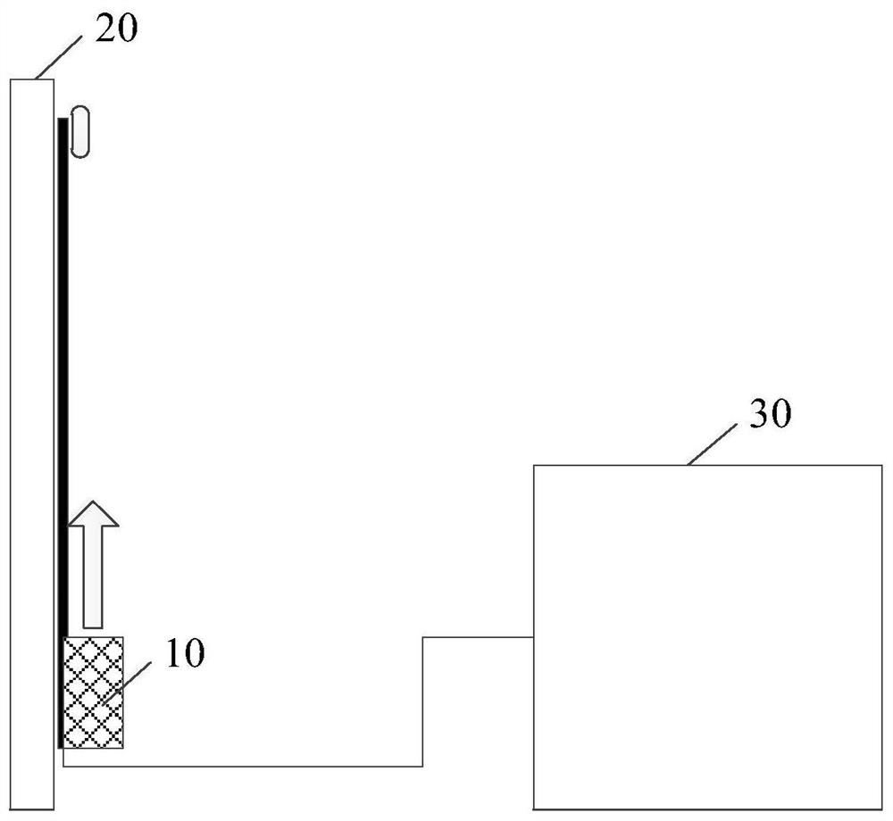
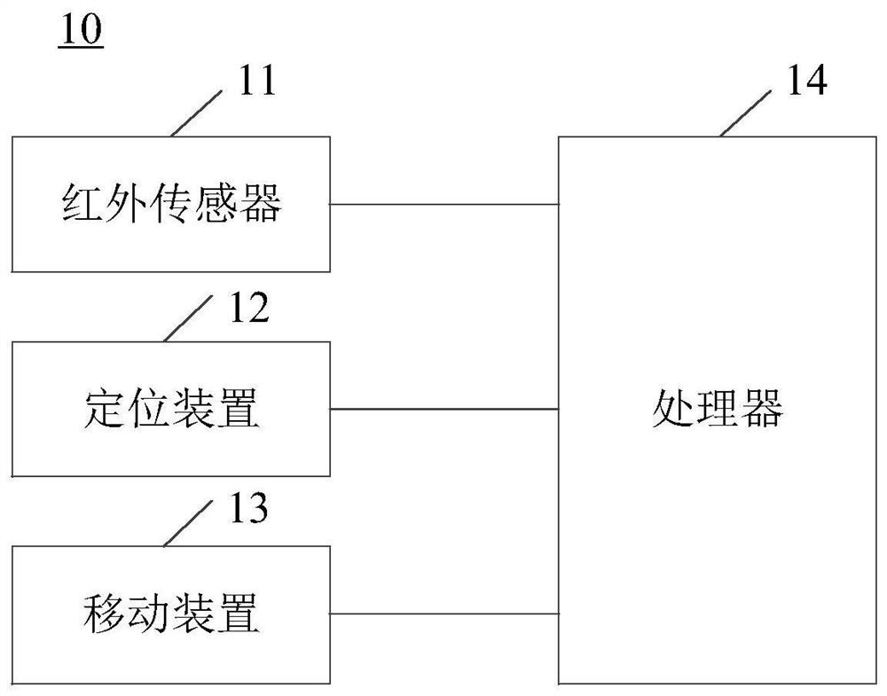
The embodiment of the invention provides optical cable detection equipment, system and method. The equipment comprises an infrared sensor, a positioning device, a moving device and a processor, wherein the processor is respectively connected with the infrared sensor, the positioning device and the moving device. The infrared sensor is used for monitoring infrared detection data on an optical cable line in real time; the positioning device is used for acquiring position information of the optical cable detection equipment in real time; the moving device is used for moving on the optical cable line according to the driving instruction of the processor; and the processor is used for obtaining the real-time position of the optical cable detection equipment in the positioning device when receiving the infrared detection data sent by the infrared sensor, and sending the real-time position to the terminal equipment. The optical cable detection equipment can replace maintenance personnel to execute a detection task of a high-altitude optical cable line, all-weather monitoring is realized, and the detection efficiency of the optical cable line is greatly improved.

Description

technical field [0001] The embodiments of the present invention relate to the technical field of optical cable detection, and in particular, to an optical cable detection device, system and method. Background technique [0002] With the continuous development of mobile communication technology, the mobile communication industry relies more on optical fiber to transmit signals. Optical fiber communication has the advantages of large capacity, small attenuation, small size, light weight, anti-interference, and saving non-ferrous metals. The laying of optical cables has become the first choice of major operators. [0003] For operators, timely detection of cable faults and hidden dangers can greatly reduce the occurrence of cable interruptions and improve communication service quality. At present, the existing optical cable detection scheme is relatively simple, mainly relying on the optical power meter to detect whether the optical cable is faulty, and often performs passive ...

Claims


Application Information

Patent Timeline
Patent Type & Authority Applications(China)
IPC IPC(8): H04B10/077
CPCH04B10/077H04B10/0771
Inventor 问航周锦伟李耀军邹卫新黎卫
Owner CHINA UNITED NETWORK COMM GRP CO LTD
Learn More