
Method for rapidly detecting solidification tail end position of continuous casting billet

A technology of solidification end and continuous casting slab, which is applied in the preparation of test samples, the configuration of indicating equipment/measuring equipment, sampling devices, etc., and can solve the problems of many external influence factors, high risk, difficult transportation, procurement, etc. , to achieve the effects of strong operability, simple process flow and high detection accuracy

Pending Publication Date: 2021-12-17
WUHU XINXING DUCTILE IRON PIPES
View PDF0 Cites 0 Cited by
  • Summary
  • Abstract
  • Description
  • Claims
  • Application Information

AI Technical Summary

Problems solved by technology

At present, most steel mills in China use online slab nailing method, online perfusion tracer method, theoretical model measurement algorithm and other methods to detect the solidification end of continuous casting slab. The disadvantages of the first two methods are: 1) The operating area of ​​the operator is close to the high temperature Molten steel / continuous casting billet has a low safety factor and high risk; 2) Most of the raw materials used (such as nail guns, steel nails, tracers) are national security control items, which are difficult to transport and purchase
The disadvantage of the latter method is that it is more affected by external factors and the accuracy of the results is poor.
Therefore, the problem of detecting the solidification end position of the continuous casting slab has not been effectively solved

Method used


Image

  • Method for rapidly detecting solidification tail end position of continuous casting billet
  • Method for rapidly detecting solidification tail end position of continuous casting billet
  • Method for rapidly detecting solidification tail end position of continuous casting billet

Examples


Embodiment Construction

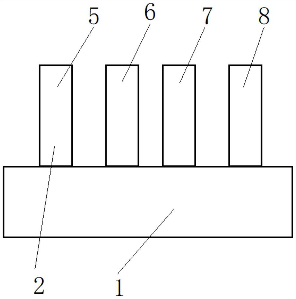
[0028] Below with reference to the accompanying drawings, through the description of the embodiments, the specific embodiments of the present invention, such as the shape, structure, mutual position and connection relationship between the various parts, the role and working principle of the various parts, etc., will be further described. Detailed instructions:

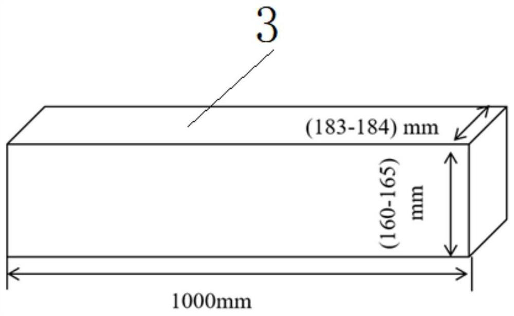
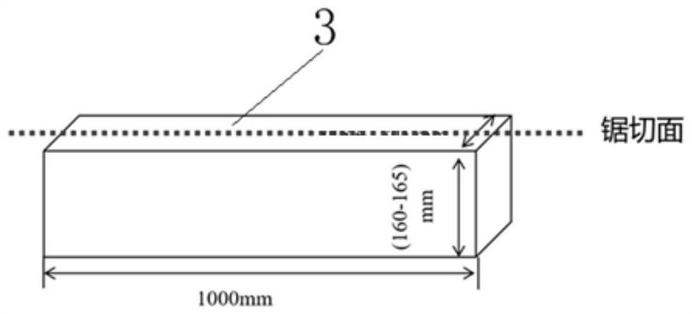
[0029] as attached figure 1 - attached Figure 4As shown, the present invention is a method for quickly detecting the solidification end position of a continuous casting slab, and the detection steps of the method for rapidly detecting the solidification end position of a continuous casting slab are: S1. Multiple rollers 2 of the leveling machine 1 sequentially press down the continuous casting slab, and the rollers 2 apply pressure in the direction of the inner and outer arcs of the continuous casting slab during the pressing; S2. The continuous casting slab after each roller 2 is pressed is respectively cut and take...


PUM


Abstract

The invention provides a method for rapidly detecting a solidification tail end position of a continuous casting billet. The method is applied to the technical field of continuous casting billet production processes. The method comprises the detection steps of enabling a roller (2) of a withdrawal and straightening machine (1) to apply pressure in the inner arc direction and the outer arc direction of the continuous casting billet; respectively cutting and taking down the pressed samples (3), and dissecting the pressed samples (3); after the plurality of pressed samples (3) are split, turning and grinding the split surfaces, and soaking the pressed samples (3) in a pickling tank; and comparing different pressed samples (3) formed by depressing different rollers (2) with non-pressed samples (4) respectively. According to the method for rapidly detecting the solidification tail end position of the continuous casting billet, a certain pressure is applied to the continuous casting billet through the withdrawal and straightening machine of a continuous casting machine, the position of the solidification tail end of the continuous casting billet can be rapidly and accurately judged, meanwhile, personnel do not need to be close to the high-temperature molten steel / continuous casting billet, additional investment and equipment transformation do not need to be increased, the operability is high, the technological process is simple, and the detection accuracy is high.

Description

technical field [0001] The invention belongs to the technical field of continuous casting slab production technology, and more specifically relates to a method for quickly detecting the solidification end position of continuous casting slab. Background technique [0002] The production process of the continuous casting machine includes injecting molten steel into the tundish, and then the tundish distributes the molten steel to the crystallizer of each flow, through which the molten steel is rapidly solidified to form a solid billet shell, and then enters the secondary cooling area of ​​the continuous casting machine to continue After cooling, the solid billet shell will gradually thicken. After the liquid steel is completely solidified, it will be cut and put into stacks and transferred to the next process. The position where the molten steel is about to completely solidify (or where the molten steel is completely viscous) is called the solidification end position of the co...

Claims


Application Information

Patent Timeline
IPC IPC(8): G01N1/04G01N1/28B22D11/16B22D2/00
CPCG01N1/04G01N1/28B22D11/16B22D2/00Y02P10/20
Inventor 黄雁左小坦刘光绪石春阳杨伟勇赵立张亚兵王吾磊
Owner WUHU XINXING DUCTILE IRON PIPES
Learn More