Construction method of tunnel structure for manual and mechanical combined obstacle removal of water-rich sand layer

A water-rich sand layer and tunnel structure technology, applied in tunnels, tunnel linings, earthwork drilling and mining, etc., can solve problems such as difficulty in ensuring engineering safety and personnel safety, unsuitable uplift piles, and low stability of sand layers, achieving Ensure long-distance freezing effect, improve passability, and freeze the effect of small range

Pending Publication Date: 2021-12-17
CHANGJIANG SURVEY PLANNING DESIGN & RES
View PDF8 Cites 0 Cited by
  • Summary
  • Abstract
  • Description
  • Claims
  • Application Information

AI Technical Summary

Problems solved by technology

[0005] When the existing underground station is located in a stratum with good stability and not rich in groundwater, various underground structures can be manually excavated by taking necessary advance pre-reinforcement measures; when the existing underground station is located in a water-rich sand layer The stability of the sand layer is low, and it is easy to cause water gushing and sand gushing under the action of groundwater. The common advanced pre-reinforcement measures are difficult to guarantee the safety of the project and the safety of personnel.
[0006] For example, the patent CN201710607908.2 provides a construction method for a subway tunnel to pass through the underground diaphragm wall of a subway station. Although this method can pass through underground obstacles, there are the following problems: 1. Shield tunneling is required, and there are certain risks; 2. It is not applicable to the situation where there are uplift piles in the lower part of the existing station

Method used


Image

  • Construction method of tunnel structure for manual and mechanical combined obstacle removal of water-rich sand layer
  • Construction method of tunnel structure for manual and mechanical combined obstacle removal of water-rich sand layer
  • Construction method of tunnel structure for manual and mechanical combined obstacle removal of water-rich sand layer

Examples


Embodiment Construction

[0039] The present invention will be further described in detail below in conjunction with the accompanying drawings and specific embodiments to facilitate a clear understanding of the present invention, but they do not limit the present invention.

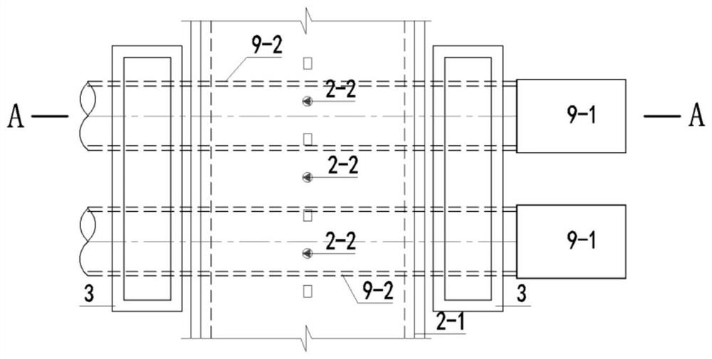
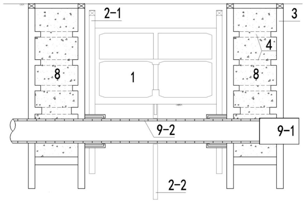
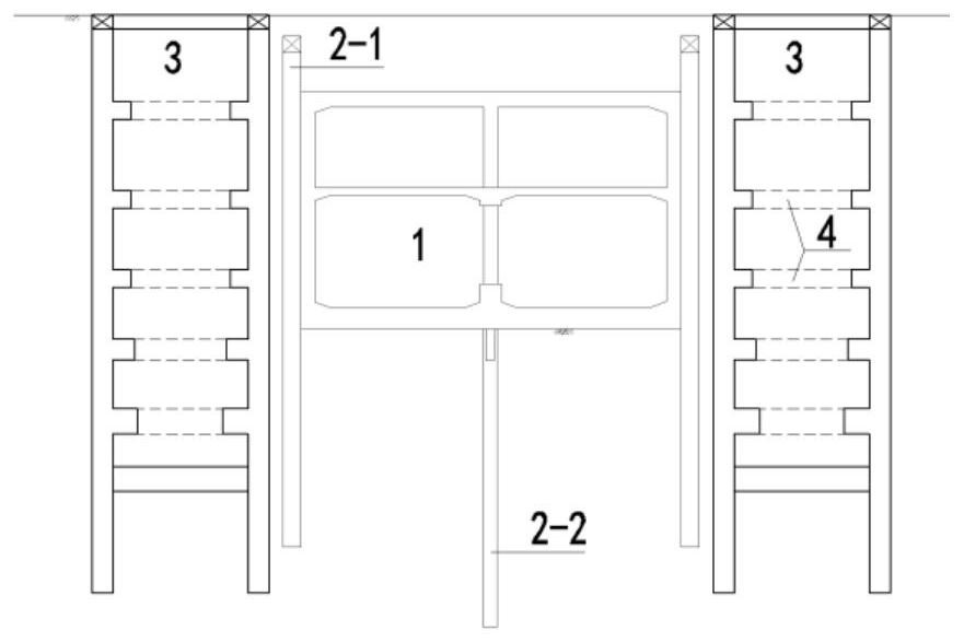
[0040] Such as Figure 3-10 As shown in the present invention, a construction method for a tunnel structure with artificial mechanical combination of water-rich sand layers, comprising the following steps: constructing the ground shafts 3 on both sides of the existing underground station 1, and performing horizontal freezing from the inside of the ground shafts 3 on both sides And two closed and disconnected frozen wall structures 5-2 are formed in the existing underground station 1, and the frozen wall structures 5-2 are frozen by salt water to form a cylindrical reinforced soil body with a certain strength and water-stop performance. Support 6-1, remove the ground connection wall 2-1 of the underground obstacle within the shield...


PUM


Abstract

The invention discloses a construction method of a tunnel structure for manual and mechanical combined obstacle removal of a water-rich sand layer. The construction method comprisies the steps that 1, ground shafts on the two sides of an existing underground station are constructed; 2, horizontal freezing is conducted from the inner sides of the ground shafts on the two sides, and two closed freezing wall structures which are not communicated are formed in the existing underground station; 3, short-distance mining method tunnel excavation construction is conducted under protection of a freezing wall structure, an underground diaphragm wall in the existing underground station is broken, a primary support is constructed, the upper portion and the lower portion of the cut-off underground diaphragm wall are connected with the primary support, and a secondary lining is constructed; 4, cement paste is injected through a grouting pipe for forced unfreezing, and concrete is backfilled into a ground shaft, primary supporting and secondary lining are achieved; and 5, tunneling construction is conducted through a shield tunneling machine, a mining method tunnel on one side is opened to the mining method tunnel on the other side, cutting is conducted through a cutter head of the shield tunneling machine, the shield tunneling machine passes through uplift piles or temporary stand columns in the middle, and segments are assembled in a shield excavation contour after cutting is completed to form a tunnel.

Description

technical field [0001] The invention relates to the technical field of tunnel engineering, in particular to a construction method for a tunnel structure in a water-rich sand layer combined with artificial machinery for obstacle removal. Background technique [0002] With the rapid development of urban rail transit engineering construction, the line network planning is constantly being updated, resulting in some stations not reserving the engineering construction conditions of the later lines during the early construction process, which directly restricts the construction plan of new projects. [0003] During the construction period of the original standard underground station, new lines were not considered in the later period. Therefore, various underground structures left underground, such as enclosure piles or ground connection walls, uplift piles or temporary columns, etc., only meet the requirements of their own force calculations. When the tunnel of the new line passes ...

Claims


Application Information

Patent Timeline
Patent Type & Authority Applications(China)
IPC IPC(8): E21D5/00E21D9/00E21D9/08E21D11/08E21D11/18E21D11/10
CPCE21D5/00E21D9/001E21D9/008E21D9/08E21D11/08E21D11/18E21D11/10
Inventor 朱敏冯东阳陈涛梅若非夏磊宋涛茹文恺孙盼赵小虎唐建一
Owner CHANGJIANG SURVEY PLANNING DESIGN & RES
Why Eureka
Try Eureka