Ophthalmic camera storage device

A storage device and camera technology, applied in packaging, transportation and packaging, and packaging item types, etc., can solve problems such as easy dust absorption of equipment, potential safety hazards of equipment, accidental collisions, etc., to ensure safe and smooth operation and avoid reduction in work efficiency , Guarantee the effect of equipment safety

Pending Publication Date: 2021-12-17
上海圣为医疗科技有限公司
View PDF7 Cites 1 Cited by
  • Summary
  • Abstract
  • Description
  • Claims
  • Application Information

AI Technical Summary

Problems solved by technology

[0003] Due to the high cost of the equipment, it is very necessary to protect the equipment. When the equipment is idle after daily use, there may be accidental collisions and misoperations by medical staff. At the same time, the equipment is easy to absorb dust in the air, which brings Therefore, in order to protect the equipment, the present invention proposes an eye camera storage device

Method used


Image

  • Ophthalmic camera storage device
  • Ophthalmic camera storage device
  • Ophthalmic camera storage device

Examples


Embodiment 1

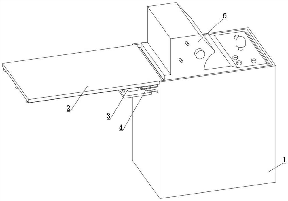
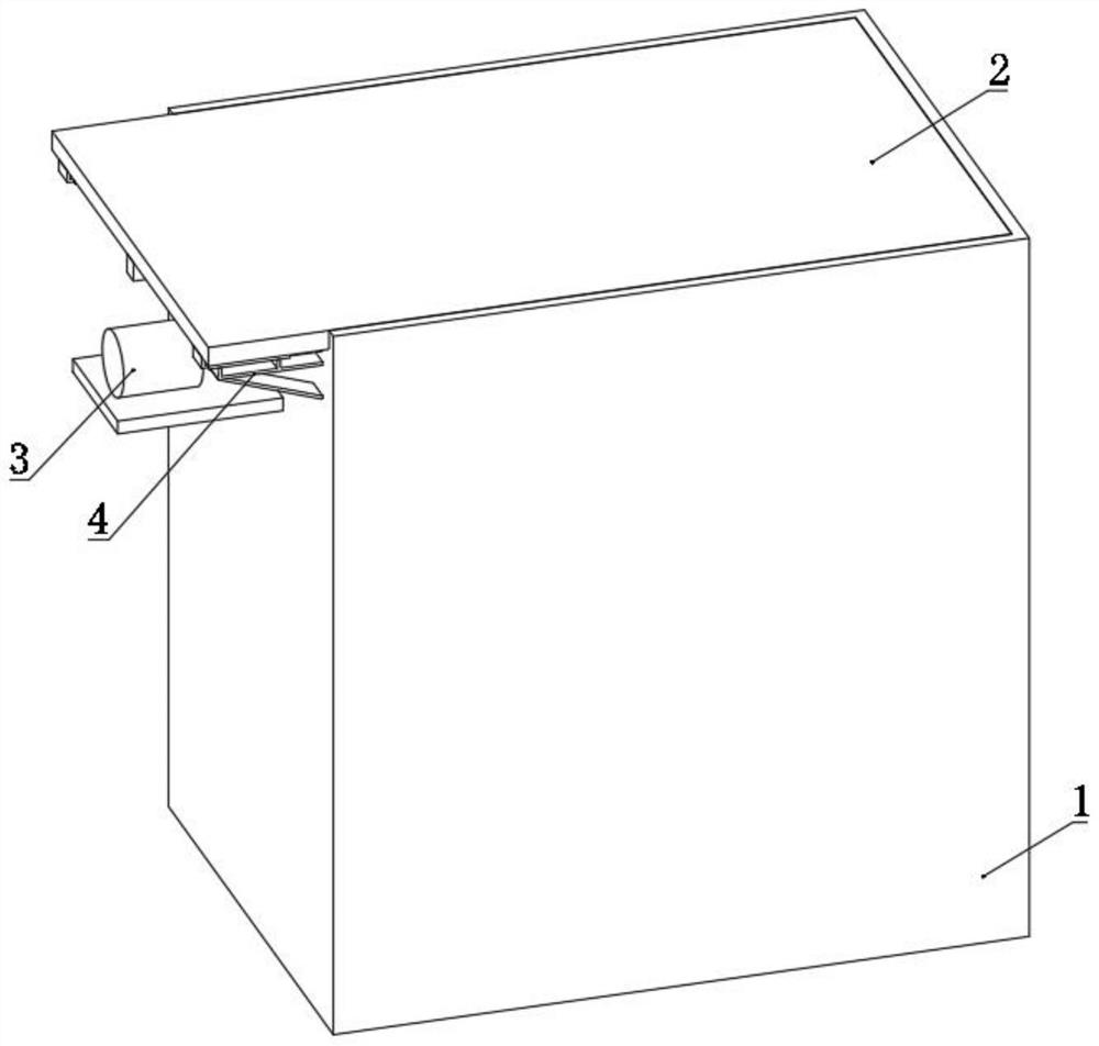
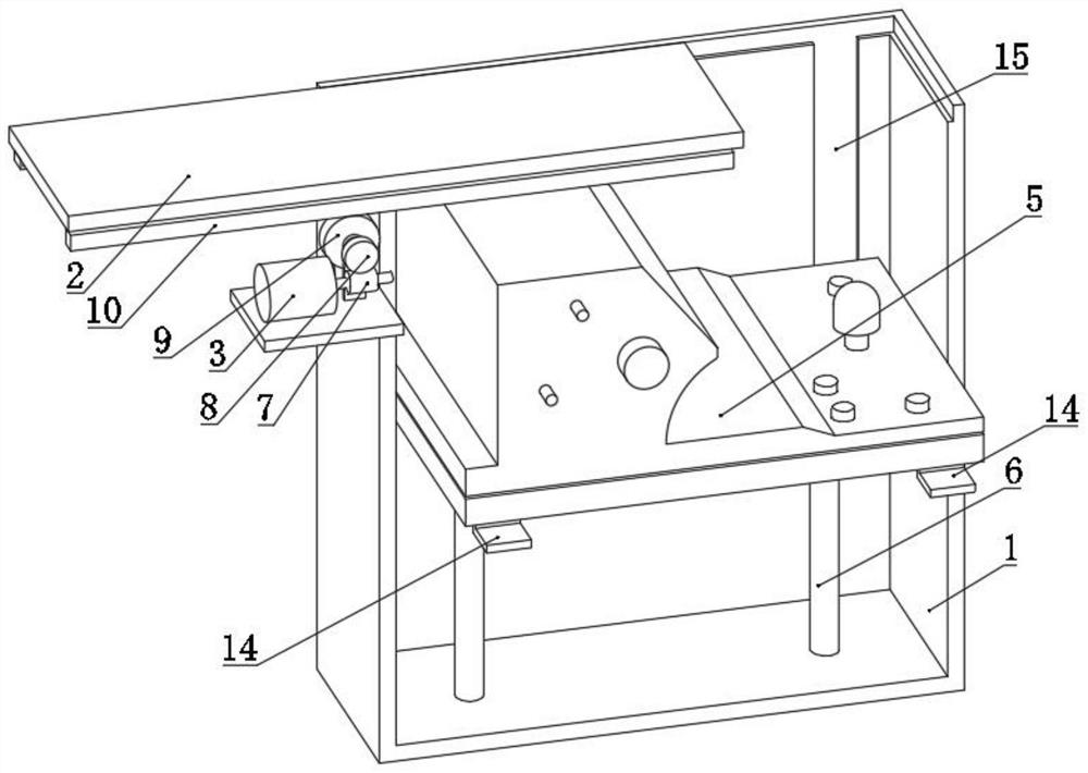
[0031] refer to Figure 1-4 , a storage device for an eye camera, comprising a box body 1, a box cover 2 is provided on the upper side of the box body 1, an electric lift rod 6 is installed on the inner bottom wall of the box body 1, the telescopic end of the electric lift rod 6 is upward and Installed with the bottom wall of the housing of the fundus camera 5, the inner wall of the box body 1 is provided with a chute 15, and slide blocks 14 are installed on both sides of the bottom of the fundus camera 5 housing, and the slide block 14 is slidably matched with the chute 15.

[0032] The case cover 2 can be opened and closed at the upper end of the case body 1. When the case cover 2 is opened, the fundus camera 5 can be lifted from the inside of the case body 1 by the electric elevating rod 6. After rising, the medical staff can operate and use it. The state after rising is as figure 1 shown.

[0033] In the process of raising and lowering the fundus camera 5, the stability ...

Embodiment 2

[0039] refer to Figure 5-6 , In the second embodiment, an exhaust pipe 16 is installed on one side of the bottom of the box body 1, and a protective net is installed inside the exhaust pipe 16. The inner bottom wall of casing 1 is equipped with heat dissipation motor 17, and the driving end of heat dissipation motor 17 is installed with fan 18 by the inner bottom wall of mounting seat and casing 1, and fan 18 is corresponding with exhaust pipe 16. There is a gap between the inner wall of the top of the box body 1 and the housing of the fundus camera 5 .

[0040] When the heat dissipation motor 17 drives the fan 18 to rotate, the heat generated by the fundus camera 5 during operation is discharged from the inside of the casing 1 through the exhaust pipe 16, thereby realizing heat dissipation treatment.


PUM


Abstract

The invention discloses an ophthalmic camera storage device, and belongs to the field of ophthalmology equipment. The ophthalmic camera storage device comprises a box body, a box cover is arranged on the upper side of the box body, an electric lifting rod is installed on the inner bottom wall of the box body, and the telescopic end of the electric lifting rod faces upwards and is installed on the bottom wall of a shell of a fundus camera. An automatic opening and closing mechanism is installed on one side of the top of the box body, and a rack and a U-shaped sliding plate are installed on the bottom wall of the box cover. The fundus camera can be stored and protected when being not in use, accidental damage to the fundus camera caused by accidental collision of personnel, misoperation and dust is avoided, equipment safety is guaranteed, property losses are avoided, meanwhile, heat dissipation treatment can be conducted on the equipment during equipment operation, and efficient operation and use of the equipment are guaranteed.

Description

technical field [0001] The invention relates to the technical field of ophthalmic equipment, in particular to an ophthalmic camera storage device. Background technique [0002] Digital retinal cameras can observe and accurately record infant retinal images, and have been used in the examination of retinal pathology (ROP) in recent years. [0003] Due to the high cost of the equipment, it is very necessary to protect the equipment. When the equipment is idle after daily use, there may be accidental collisions and misoperations by medical staff. At the same time, the equipment is easy to absorb dust in the air, which brings Therefore, in order to protect the equipment, the present invention proposes a storage device for an eye camera. Contents of the invention [0004] The object of the present invention is to propose a storage device for an eye camera to solve the defects in the prior art. [0005] In order to achieve the above object, the present invention adopts the fol...

Claims


Application Information

Patent Timeline
Patent Type & Authority Applications(China)
IPC IPC(8): B65D81/26B65D85/38
CPCB65D81/261B65D85/38
Inventor 王林
Owner 上海圣为医疗科技有限公司
Why Eureka
Try Eureka