
Rotor assembly of linear displacement sensor and linear displacement sensor

A linear displacement sensor and mover technology, applied in the field of sensors, can solve problems such as inability to install or difficult installation, single operation mode, narrow installation application range, etc., and achieve the effects of improving service life, increasing reliability, and improving mechanical properties

Pending Publication Date: 2021-12-14
BEIJING XINGKONG JIANTENG ELECTRONICS TECH CO LTD
View PDF0 Cites 0 Cited by
  • Summary
  • Abstract
  • Description
  • Claims
  • Application Information

AI Technical Summary

Problems solved by technology

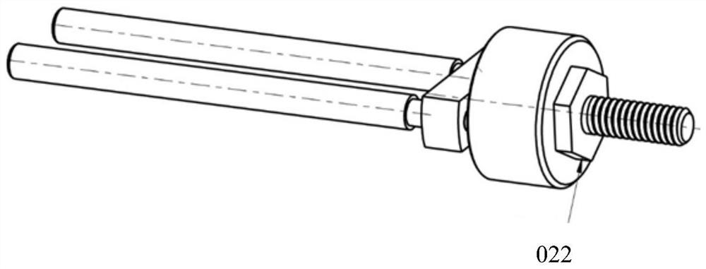
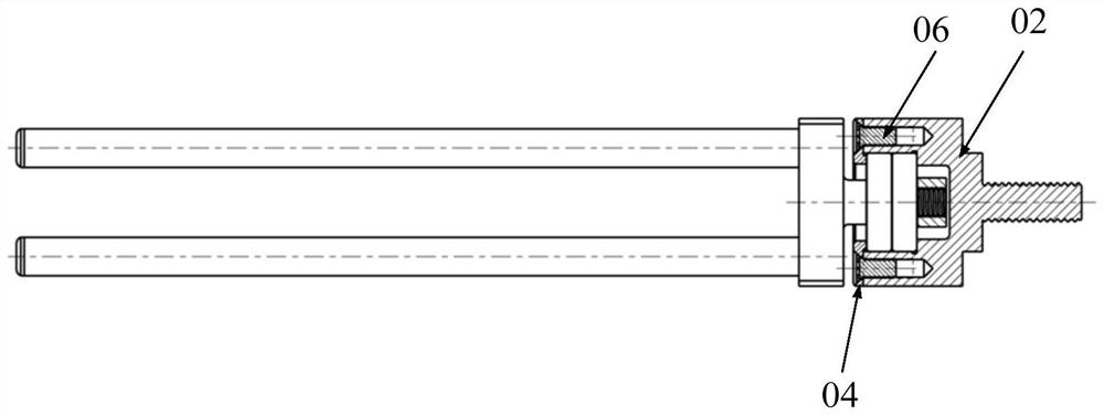
[0003] The installation of the current mover assembly is mainly through the connecting thread 021 on the moving rod 02 and the position to be installed is fixed. During installation, the outer hexagon 022 provided on the moving rod 02 is mainly rotated to rotate the connecting thread 021 on the moving rod 02. The outer hexagon 022 is located on the side of the magnetic core base 01 away from the magnetic core assembly 07 installed on it, that is, the operation can only be done when the magnetic core base 01 is away from the magnetic core assembly 07 installed on it. One side of the operation, the operation method is relatively simple, when the position to be installed is a deep cavity or a blind hole, it cannot be installed or the installation is difficult, and the scope of installation is narrow

Method used


Image

  • Rotor assembly of linear displacement sensor and linear displacement sensor
  • Rotor assembly of linear displacement sensor and linear displacement sensor
  • Rotor assembly of linear displacement sensor and linear displacement sensor

Examples


Embodiment Construction

[0050] The present invention will be described in further detail and complete below in conjunction with specific embodiments. The following description is merely exemplary in nature and not intended to limit the disclosure, application or use.

[0051]Taking the linear differential transformer displacement sensor as an example, the principle of the linear differential transformer is briefly explained. The linear differential transformer displacement sensor is an inductive sensor that converts non-electrical mechanical displacement changes into proportional electrical parameter changes. When ignoring the coil parasitic capacitance and core loss, the equivalent circuit of the linear displacement sensor Figure 4 shown.

[0052] in Figure 4 middle: e 1 is the excitation voltage of the primary coil; L 1 , R 1 are the primary coil inductance and resistance respectively; L 21 , L 22 are the inductances of the two secondary coils; M 1 , M 2 Respectively, the primary and two...


PUM


Abstract

The invention discloses a rotor assembly of a linear displacement sensor and a linear displacement sensor. The rotor assembly and the linear displacement sensor have good applicability and installation convenience. The rotor assembly comprises a magnetic core seat body, a moving rod, a magnetic core piece, two angle joint bearings and a bearing inner end cover; a first mounting operation part is arranged on the moving rod; a second mounting operation part is arranged at one end of the moving rod; and a connecting part is arranged at the other end of the moving rod; the bearing inner end cover is in threaded connection with the end, provided with the second mounting operation part, of the moving rod; the two angle joint bearings are installed on the moving rod in a back-to-back mode and located between the bearing inner end cover and the first mounting operation part; and the first mounting operation part or the second mounting operation part is operated so that the connecting part on the moving rod can be fixedly connected with a position to be installed; and one end of the magnetic core seat body is fixed relative to the outer rings of the angle joint bearings, the other end of the magnetic core seat body is provided with the magnetic core piece; and the end, provided with the magnetic core piece, of the magnetic core seat body is provided with an avoiding part communicated with the second mounting operation part.

Description

technical field [0001] The invention relates to the technical field of sensors, in particular to a mover assembly of a linear displacement sensor and a linear displacement sensor. Background technique [0002] The dual-redundancy linear displacement sensor is widely used in the fly-by-wire flight control system and engine system of aviation aircraft. The purpose of its dual-redundancy design is that when one set of winding coils fails, the other set of spare windings will start to work to ensure that the sensor Normal performance output. Such as figure 1 As shown, the dual-redundancy linear displacement sensor mainly includes a mover assembly and a stator assembly. The mover assembly is an important structure for the sensor to realize its functions. The mover assembly mainly includes a magnetic core base 01, a moving rod 02, an angular contact bearing 03, and a bearing Outer end cover 04, bearing inner end cover 05, screw 06, magnetic core assembly 07, anti-backlash washer...

Claims


Application Information

Patent Timeline
Patent Type & Authority Applications(China)
IPC IPC(8): G01B7/02
CPCG01B7/02
Inventor 施立刚强朝利齐广东袁树峥
Owner BEIJING XINGKONG JIANTENG ELECTRONICS TECH CO LTD
Learn More