Method for creating and actually measuring axial temperature gradient distribution of electromagnetic gun track

A temperature gradient, electromagnetic gun technology, applied in the direction of thermometers, thermometers, electromagnetic means, etc. using directly sensitive electric/magnetic components, can solve the launch failure, affect the launch efficiency, electromagnetic launch system track thermal stress damage, etc. problem, to achieve the effect of reducing human error and small damage

Pending Publication Date: 2021-12-10
TIANJIN UNIV
View PDF0 Cites 0 Cited by
  • Summary
  • Abstract
  • Description
  • Claims
  • Application Information

AI Technical Summary

Problems solved by technology

During the launching process of the electromagnetic rail gun, because the armature and the launch rail are in high-speed sliding electrical contact, the instantaneous current is transmitted to the armature through the guide rail at high speed, causing a large amount of heat to be generated on the guide rail instantly, which is likely to cause thermal stress damage to the rail of the electromagnetic launch system
In the continuous launch mode, the electromagnetic railgun is expected to launch 6 to 12 rounds of projectiles per minute. The rapid accumulation of heat will not only affect the launch efficiency, but may also cause damage to the orbital performance, causing problems such as shortened life of the electromagnetic launch system or even launch failure.

Method used


Image

  • Method for creating and actually measuring axial temperature gradient distribution of electromagnetic gun track
  • Method for creating and actually measuring axial temperature gradient distribution of electromagnetic gun track
  • Method for creating and actually measuring axial temperature gradient distribution of electromagnetic gun track

Examples


Embodiment Construction

[0021] The present invention will be further described below through the following embodiments in conjunction with the accompanying drawings, wherein the accompanying drawings constitute a part of this application. It should be understood that the following embodiments are only used to illustrate the present invention, not to limit the present invention.
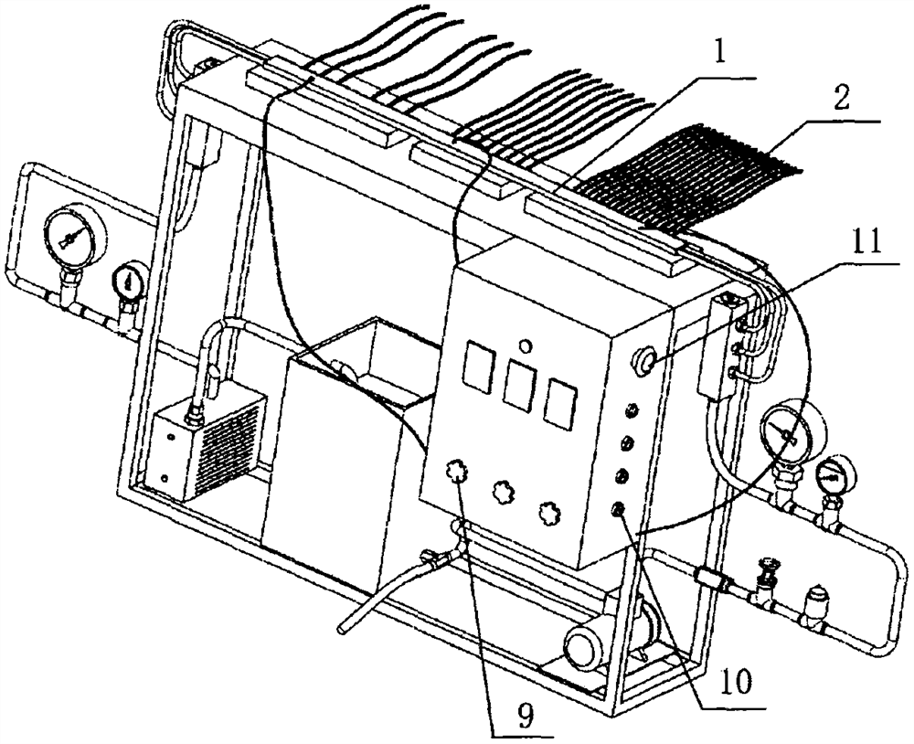
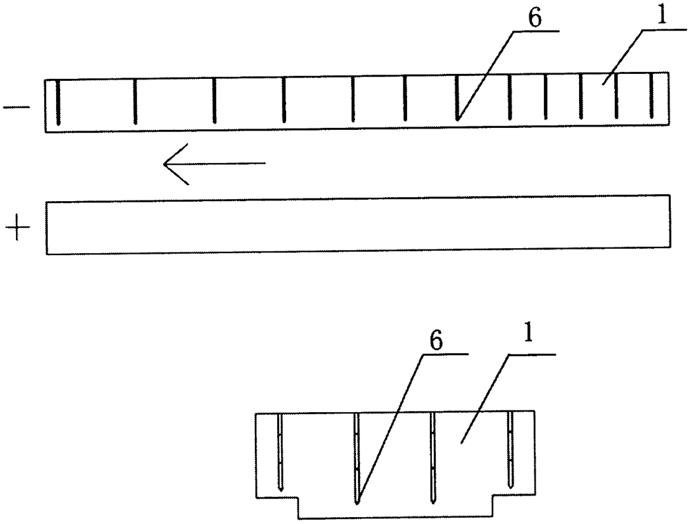
[0022] The main idea of ​​the embodiment of the present invention is: in the case of no actual missile launch, the electromagnetic copper track is heated by adjusting the quantity and power of the three groups of heating tubes 2, so as to ensure that the temperature of the temperature measuring point on the electromagnetic track reaches the preset value, and the simulated The non-uniform temperature distribution of the track at the moment of launch of the electromagnetic railgun provides an experimental basis for the study of the active cooling and heat transfer characteristics inside the electromagnetic track.

[0023] In t...


PUM


Abstract

The invention relates to a method for creating and actually measuring axial temperature gradient distribution of an electromagnetic gun track, and belongs to the technical field of electromagnetic rail guns. According to the method, an electromagnetic track is divided into a high-temperature section, a medium-temperature section and a low-temperature section on the basis of analytical calculation and public literature data, and under the condition of no actual missile launching, the electromagnetic track is heated through three sets of unequal-distance and power-adjustable heating pipes to create track temperature distribution after electromagnetic railgun launching. Temperature measuring points are arranged on the electromagnetic track and extend from the outer side of the rack to the position 1-2 mm away from the contact side of a pivot rail, a thermocouple is connected with a data acquisition instrument to obtain the real-time temperature of the temperature measuring points, and experimenters can conveniently adjust the number of the heating pipes and the heating power to achieve temperature distribution of the electromagnetic rail under various working conditions; the problem that the thermal management experiment research of the electromagnetic rail gun is difficult to carry out due to the fact that actual launching of the electromagnetic rail gun is complex is innovatively solved.

Description

technical field [0001] The invention relates to the technical field of electromagnetic railguns, in particular to a method for creating and measuring the axial temperature gradient distribution of an electromagnetic railgun rail. Background technique [0002] Electromagnetic rail gun is an advanced kinetic energy killing weapon made by electromagnetic launch technology. Its launch principle is to form a discharge circuit through electromagnetic rails and conductive armatures. High-power pulse power supply is used to generate pulsed strong current, and strong current generates strong magnetic field. The armature carrying the projectile is pushed by the Lorentz force under the action of a strong magnetic field, so as to obtain a high firing speed. During the launching process of the electromagnetic railgun, because the armature and the launch rail are in high-speed sliding electrical contact, the instantaneous current is transmitted to the armature through the guide rail at hi...

Claims


Application Information

Patent Timeline
IPC IPC(8): H05B1/02H05B3/40G01K7/02
CPCH05B1/0227H05B3/40G01K7/02
Inventor 农奥兵马洪亭马硕黄达伟颜聪
Owner TIANJIN UNIV
Why Eureka
Try Eureka