Positive plate and lithium ion battery
A technology of positive electrode sheet and positive active material, which is applied in the field of positive electrode sheet and lithium-ion battery, can solve problems such as battery damage, and achieve the effect of avoiding battery damage and improving safety
- Summary
- Abstract
- Description
- Claims
- Application Information
AI Technical Summary
Problems solved by technology
Method used
Image
Examples
Embodiment 1
[0060] An aluminum foil with a thickness of 10 microns was used as the positive electrode current collector, and the above positive electrode current collector had a multi-tab structure. The positive electrode active material coating is prepared by using the positive electrode active material, the conductive agent and the binder according to the ratio of 96:1.5:2.5. The mixed coating was prepared according to the ratio of ceramics and anti-oxidation components at 7:3.
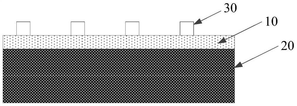
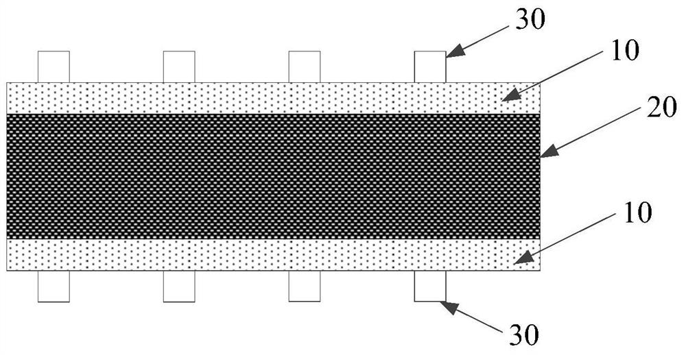
[0061] The mixed coating is coated on the first coating area 10 of the positive current collector, and the positive active material coating is coated on the second coating area 20 of the positive current collector, wherein a coating device can be used on the positive current collector to simultaneously The first coating area 10 and the second coating area 20 are coated. The mixed coating is applied to the third coating area 31 of the tab 30 . Wherein, the width of the first coating area 10 is set to be 1.5 mm...
Embodiment 2
[0066] An aluminum foil with a thickness of 10 microns was used as the positive electrode current collector, and the above positive electrode current collector had a wound structure. The positive electrode active material coating is prepared by using the positive electrode active material, the conductive agent and the binder according to the ratio of 96:1.5:2.5. The mixed coating was prepared according to the ratio of ceramics and anti-oxidation components at 7:3.
[0067] The mixed coating is coated on the first coating area 10 of the positive electrode current collector, and the positive electrode active material coating is coated on the second coating area 20 of the positive electrode current collector. One coating area 10 is coated, and then the second coating area 20 of the positive current collector is coated. The width of the first coating area 10 is set to be 105 mm.
[0068] The positive electrode sheet is obtained after drying, rolling, slitting and die-cutting the...
Embodiment 3
[0072] An aluminum foil with a thickness of 10 microns was used as the positive electrode current collector, and the above positive electrode current collector had a multi-tab structure. The positive electrode active material coating is prepared by using the positive electrode active material, the conductive agent and the binder according to the ratio of 96:1.5:2.5. The mixed coating was prepared according to the ratio of ceramics and anti-oxidation components at 7:3.
[0073] Coating the positive electrode active material coating on the second coating area 20 of the positive electrode current collector, coating the mixed coating on the first sub-coating area 11 of the positive electrode current collector, and coating the second sub-coating area 12 of the positive electrode current collector Apply the mixed positive electrode active material coating and the mixed coating, and coat the mixed coating on the third coating area 31 of the tab 30 . Wherein, the width of the second ...
PUM
| Property | Measurement | Unit |
|---|---|---|
| Particle size | aaaaa | aaaaa |
| Thickness | aaaaa | aaaaa |
| Thickness | aaaaa | aaaaa |
Abstract
Description
Claims
Application Information
 - R&D
- Intellectual Property
- Life Sciences
- Materials
- Tech Scout
- Unparalleled Data Quality
- Higher Quality Content
- 60% Fewer Hallucinations
Browse by: Latest US Patents, China's latest patents, Technical Efficacy Thesaurus, Application Domain, Technology Topic, Popular Technical Reports.
© 2025 PatSnap. All rights reserved.Legal|Privacy policy|Modern Slavery Act Transparency Statement|Sitemap|About US| Contact US: help@patsnap.com


