Shaft hole centering guide method in workpiece assembly process based on machine vision

An assembly process and machine vision technology, applied in manipulators, manufacturing tools, program-controlled manipulators, etc., can solve problems such as the inability to effectively complete the assembly process, face fixed scenes, and fail to complete pre-selected tasks well.

Pending Publication Date: 2021-12-07
BEIJING UNIV OF TECH
View PDF0 Cites 0 Cited by
  • Summary
  • Abstract
  • Description
  • Claims
  • Application Information

AI Technical Summary

Problems solved by technology

However, in the current automated assembly process, the robot can only face a fixed scene under the condition that the robot assembles according to the established working path. Once the position or posture of the workpiece changes, the assembly process cannot be effectively completed.
This leads to the fact that once the working scene changes when using industrial robots, the pre-selected tasks cannot be well completed.

Method used


Image

  • Shaft hole centering guide method in workpiece assembly process based on machine vision
  • Shaft hole centering guide method in workpiece assembly process based on machine vision
  • Shaft hole centering guide method in workpiece assembly process based on machine vision

Examples


Embodiment Construction

[0024] The following are specific implementation cases of the present invention and in conjunction with the accompanying drawings, further describe the technical solution of the present invention, but the present invention is not limited to these implementation cases.

[0025] It should also be understood that the specific embodiments described here are only for understanding the present invention, and are not intended to limit the present invention.

[0026] The target image processed by the present invention comes from the industrial camera of the industrial robot, and the industrial camera is used to detect workpieces on the production line.

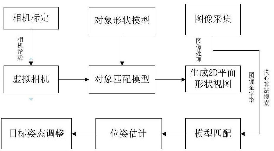
[0027] like figure 1 As shown, the step-by-step operation of a vision-based workpiece detection method proposed by the present invention is as follows:

[0028] Step 1. The model diagram of the bolt (M12) to be identified and matched (assembled) is used as a 3D object model. When creating the bolt model, the central axis of the bolt ...


PUM


Abstract

The invention discloses a shaft hole centering guide method in a workpiece assembly process based on machine vision. The method comprises the steps that a to-be-detected workpiece is shot through an industrial camera, and an image of the workpiece in a detection region is obtained; and a 3d shape model for matching is created from a 3d object model of the to-be-detected workpiece. A virtual camera is used for shooting the 3d object model in a specified attitude range, and the 3d shape model is generated through images at different visual angles. A greedy algorithm is adopted to retrieve in a specified image pyramid range, the most suitable matching object is found, the posture of the matching object is obtained, and a tail end of a robot is adjusted to perform correct shaft hole centering guide operation through posture analysis.

Description

technical field [0001] The invention relates to a detection method combined with machine vision and image recognition applied to workpiece matching and recognition in three-dimensional space. The shaft hole alignment method in the workpiece assembly process. Background technique [0002] In the context of the gradual increase in the application of intelligence and automation in the industrial production process, more and more factories have begun to develop industrial robot production lines, and more production processes have begun to be completed by robots, including automated assembly links. In the process of workpiece assembly, the centering of the shaft hole is the basis of many assembly operations. Only by correctly realizing the centering of the shaft hole can the assembly operation be completed smoothly, the assembly accuracy can be guaranteed, and the damage of the assembled workpiece can be avoided, which in turn will cause production resources. Waste and increased...

Claims


Application Information

Patent Timeline
IPC IPC(8): B25J9/16B25J19/02
CPCB25J9/1697B25J9/1687B25J19/023
Inventor 刘志峰刘康许静静杨聪彬王建华李龙飞陈建州
Owner BEIJING UNIV OF TECH
Why Eureka
Try Eureka