Multi-step inner hole machining method

A processing method and multi-step technology, applied in the field of gearboxes, can solve the problems that the machining accuracy of the multi-step inner hole structure cannot be guaranteed, the consistency of the finished product is poor, and the coaxiality is difficult to ensure, so as to improve the quality of the valve control surface and the high yield. , the effect of high processing efficiency

Pending Publication Date: 2021-12-07
CHONGQING BEIBEN TRANSMISSION MFG
View PDF0 Cites 0 Cited by
  • Summary
  • Abstract
  • Description
  • Claims
  • Application Information

AI Technical Summary

Problems solved by technology

However, the machining accuracy of the multi-step inner hole structure is not suitable to be guaranteed, and the consistency of the finished product is poor: in the existing machining and forming process, each hole is processed separately, and the coaxiality is difficult to guarantee, and it is usually necessary to replace a variety of different types of tools
At the same time, due to the existence of steps and faults, the hole roughness and cylindricity are difficult to guarantee

Method used


Image

  • Multi-step inner hole machining method
  • Multi-step inner hole machining method
  • Multi-step inner hole machining method

Examples


Embodiment 1

[0028] This embodiment provides a multi-step inner hole processing method, including the following steps:

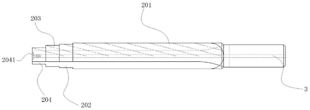
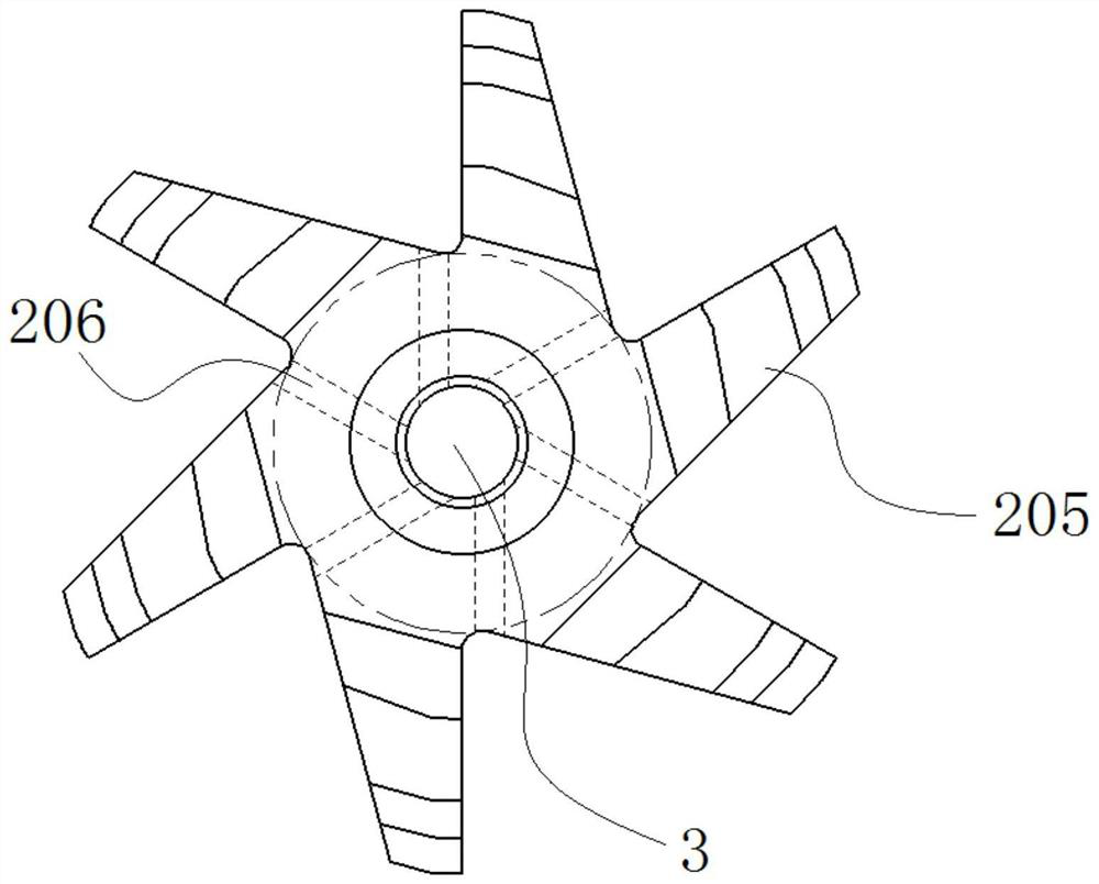
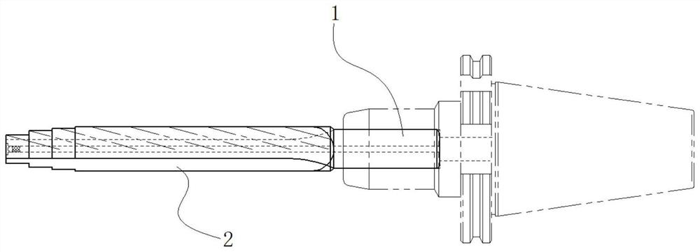
[0029] 1) Design the tool according to the structure of the multi-step inner hole 4 to be processed. Wherein, the tool includes a clamping rod 1 and a reamer rod 2 . The tool is provided with a through cooling hole 3 along the length direction. A liquid outlet hole 206 is also arranged on the body of the reamer rod 2 . The liquid outlet hole 206 communicates with the cooling hole 3 and the outside of the reamer rod 2 . The reamer rod 2 includes a first reamer head 201 , a second reamer head 202 , a third reamer head 203 and a fourth reamer head 204 arranged coaxially in sequence along a direction away from the clamping rod 1 . The first reamer head 201 , the second reamer head 202 , the third reamer head 203 and the fourth reamer head 204 are cylinders whose diameters decrease successively as a whole. The outer walls of the first reamer head 201 , the second reamer h...

Embodiment 2

[0038] This embodiment provides a basic multi-step inner hole processing method, including the following steps:

[0039] 1) Design the tool according to the structure of the multi-step inner hole 4 to be processed. Wherein, the tool includes a clamping rod 1 and a reamer rod 2 . The tool is provided with a through cooling hole 3 along the length direction. The reamer rod 2 includes a first reamer head 201 , a second reamer head 202 , a third reamer head 203 and a fourth reamer head 204 arranged coaxially in sequence along a direction away from the clamping rod 1 . The first reamer head 201 , the second reamer head 202 , the third reamer head 203 and the fourth reamer head 204 are cylinders whose diameters decrease successively as a whole. The outer walls of the first reamer head 201 , the second reamer head 202 , the third reamer head 203 and the fourth reamer head 204 are provided with cutting edges 205 with unequal tooth distribution. The fourth reamer head 204 defines a ...

Embodiment 3

[0046] The main steps of this embodiment are the same as those of Embodiment 2, wherein the outer wall of the clamping rod 1 is a smooth surface. The outer wall of the reamer rod 2 is covered with superhard abrasives. The grain sizes of the first reamer head 201 , the second reamer head 202 , the third reamer head 203 and the fourth reamer head 204 are different.


PUM


Abstract

The invention provides a multi-step inner hole machining method. The machining method comprises the steps of designing a cutter according to the structure of a to-be-machined multi-step inner hole, carrying out a process test, machining a workpiece blank, carrying out rough reaming, carrying out semi-finish reaming, carrying out finish reaming and the like. The machining method is high in machining efficiency, the coaxial precision of stepped holes is high, tool connecting marks caused by repeated tool changing are avoided, the valve control surface quality is improved, and the rate of finished products is high; the procedures of polishing, cleaning and rust prevention are added; and the problems that the machining size of the high-precision and multi-step inner hole is unstable, the form and location tolerance and roughness are low, and the drawing requirements of products are difficult to meet are solved. The method can be widely applied to precise valve hole machining of parts such as AT gearbox valve bodies and front supports.

Description

technical field [0001] The invention relates to the technical field of gearboxes, in particular to a multi-step inner hole processing method. Background technique [0002] There are many multi-step inner hole structures on the AT transmission valve body and the front support. The quality requirements of each hole are very strict, such as precision grade 6, roughness Ra0.4, cylindricity 0.003, coaxiality 0.005, etc. However, the machining accuracy of the multi-step inner hole structure is not suitable to be guaranteed, and the consistency of the finished product is poor: in the existing machining and forming process, each hole is processed separately, and the coaxiality is difficult to guarantee, and it is usually necessary to replace a variety of different types of tools. At the same time, due to the existence of steps and faults, the hole roughness and cylindricity are difficult to guarantee. [0003] Therefore, the development of a multi-step inner hole processing method...

Claims


Application Information

Patent Timeline
Patent Type & Authority Applications(China)
IPC IPC(8): B23P15/00
CPCB23P15/00
Inventor 周友国王虎陈绍龙吴玉邱方冬姜峰梅杰
Owner CHONGQING BEIBEN TRANSMISSION MFG
Why Eureka
Try Eureka